Download
1 / 21
210 likes | 293 Views
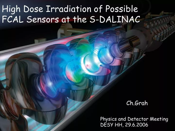
High Dose Irradiation of Possible FCAL Sensors at the S-DALINAC. Ch.Grah Physics and Detector Meeting DESY HH, 29.6.2006. Contents. Reminder of FCAL detector systems and motivation Testbeam at the S-DALINAC of the TU Darmstadt (12.06. -19.06.2006) Preparations

E N D
High Dose Irradiation of Possible FCAL Sensors at the S-DALINAC Ch.Grah Physics and Detector MeetingDESY HH, 29.6.2006
Contents • Reminder of FCAL detector systems and motivation • Testbeam at the S-DALINAC of the TU Darmstadt (12.06. -19.06.2006) • Preparations • Some pictures from the testbeam • Analysis and first results • Summary Ch.Grah: FCAL Testbeam 2006
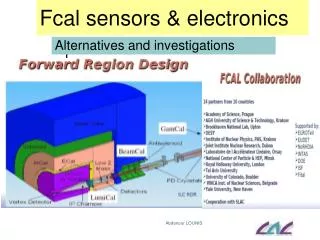
FCAL System Forward region of LDC (V2) LumiCal 30 layer Si:W 26 < θ < 155 mrad BeamCal 30 layer CVD diamond:W 5 < θ < 28 mrad Ch.Grah: FCAL Testbeam 2006
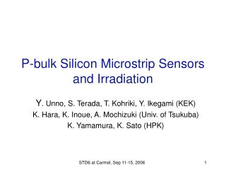
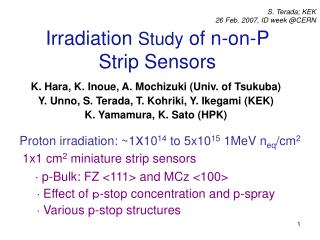
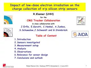
Sensors for FCAL Investigate: • pCVD diamond sensors from different manufacturers (E6, IAF, Minsk) • Si sensors • GaAs sensors Energy deposition from beamstrahlung pairs in BeamCal. 10-20 TeV and more depending on the beam parameters. Dose of up to 10MGy/a pCVD sensor from IAF 12 x 12 mm2 size, 300-500μm thickness, Ti/Pt/Au metallization IAF: Fraunhofer Institute for Applied Solid-State Physics E6: De Beers Industrial Diamonds rebranded to Element Six in 2002 pCVD: polycrystaline Chemical Vapour Deposition Ch.Grah: FCAL Testbeam 2006
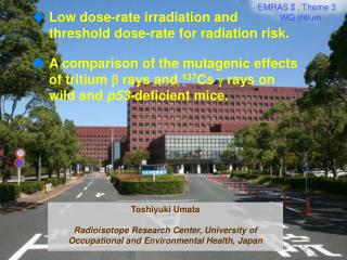
Radiation Hardness of CVD diamonds „pCVD diamonds are radiation hard.“ In our lab: so far only low dose irradiation T.Behnke et al., 2001 diamond response vs. absorbed dose (Sr90) Ch.Grah: FCAL Testbeam 2006
Testbeam Purpose: High Dose Irradiation • Irradiate different sensor samples to high doses (>1 MGy). • Use rather low energetic electrons similar to secondaries. Energy spectrum of particles depositing energy in the BeamCal sensors V.Drugakov 2X0 6X0 20X0 Ch.Grah: FCAL Testbeam 2006
S-DALINAC of the TU Darmstadt • Using the injector line of the S-DALINAC: 10± 0.015 MeV and beam currents from 10 to 100 nA Superconducting DArmstadt LInear ACcelerator 3 GHz electron beam energy: 2.5 to 130 MeV intensity: 1 nA to 50 µA Ch.Grah: FCAL Testbeam 2006
Accelerator Hall Ch.Grah: FCAL Testbeam 2006
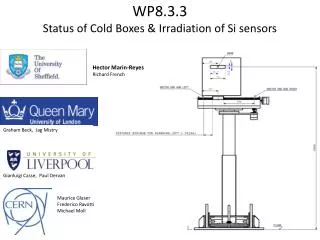
S-DALINAC Location Beam Area see next slide CCD setup Periodic Charge Collection Distance measurement Remote control/surveillance of beam area Transport of sensor under HV Ch.Grah: FCAL Testbeam 2006
Beam Area Optimization by G4 simulation Monitor beam current via Faraday cup current to estimate dose. Monitor high voltage/current and temperatures. Local DAQ PC is operated remotely. Ch.Grah: FCAL Testbeam 2006
G4 Simulation Optimize collimator and Faraday cup size Optimize distance Reduce distance to exit window Ch.Grah: FCAL Testbeam 2006
G4 Simulation Statistics (extract R = NFC/NSensor = 0.98) Energy deposition in the sensor Spatial distribution of sensor hits Ch.Grah: FCAL Testbeam 2006
Sensor Holder exit window of beam line collimator (IColl) Faraday cup (IFC, TFC) sensor box (IDia, TDia, HV) Ch.Grah: FCAL Testbeam 2006
Beam Area: Equipment Sensor holder I-V conversion Power supplies and monitoring Surveillance from control room Ch.Grah: FCAL Testbeam 2006
Beam Area: Sensor (De-) Installation Ch.Grah: FCAL Testbeam 2006
CCD Setup Installation Ch.Grah: FCAL Testbeam 2006
CCD Setup Operation PA Sr90 ADC diamond delay Sr90 source Scint. discr PM1 & Gate discr PM2 Preamplifier Sensor box Trigger box typical spectrum of an E6 sensor Ch.Grah: FCAL Testbeam 2006
Program • 2 samples from E6 • 1 MGy • 5 MGy • 2 samples from IAF • 1 MGy • 5 MGy • 2 Si samples • both drew high currentsafter ~50 kGy. E6_4p after ~5 MGy Ch.Grah: FCAL Testbeam 2006
Analysis and First Preliminary Results • Tuned the beam to currents in the Faraday cup of: • 10, 20, 50 and 100 nA • This corresponds to dose rates of: • 59, 118, 296, 591 kGy/h • For now assume an error of 10%. Preliminary Preliminary Ch.Grah: FCAL Testbeam 2006
Conclusion • Investigated the radiation hardness of sensors (silicon and pCVD diamond) for the calorimeters of the FCAL system of the ILC. • The S-DALINAC offers an infrastructure for irradiating with a wide range of intensities and energies up to 10 MeV. • Irradiated 6 samples up to doses of 1-5 MGy (at least for the diamond sensors). • Analysis is ongoing. • Have the opportunity to repeat such a test next year, to irradiate to even higher doses. • There were some issues (beam monitoring during irradiation, sensor box design) which will be improved by then. Ch.Grah: FCAL Testbeam 2006
The Testbeam Crew not on the photo: W.Lange Thanks to: INTAS and the TU Darmstadt Ch.Grah: FCAL Testbeam 2006