Download
1 / 11
110 likes | 226 Views
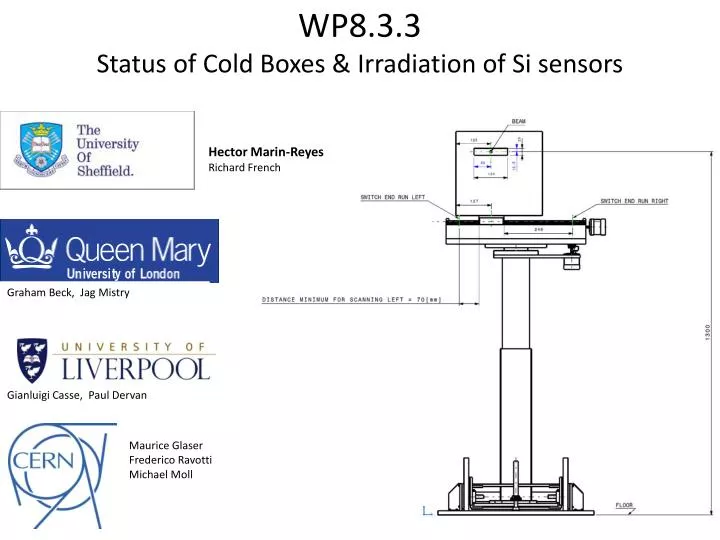
Hector Marin-Reyes Richard French. WP8.3.3 Status of Cold Boxes & Irradiation of Si sensors. Graham Beck, Jag Mistry. Gianluigi Casse , Paul Dervan. Maurice Glaser Frederico Ravotti Michael Moll. Task 8.3. – Upgrade of PS proton and mixed-field irradiation facilities at CERN.

E N D
Hector Marin-Reyes Richard French WP8.3.3 Status of Cold Boxes & Irradiation of Si sensors Graham Beck, Jag Mistry GianluigiCasse, Paul Dervan Maurice Glaser FredericoRavotti Michael Moll
Task 8.3. – Upgrade of PS proton and mixed-field irradiation facilities at CERN Task Overview • Task leader: Michael Moll (CERN) • Objectives: • Improvement of existing irradiation facilities at CERN PS • Elaboration and evaluation of upgrade scenarios • Design and test of common infrastructure for the facility • Sub-tasks and participants • 8.3.1. Improvement of existing irradiation facilities and evaluation of upgrade scenariosCERN • 8.3.2/3 Common infrastructure for the facilitiesCERN, UNILIV, USFD - (Irradiation tables and boxes) VU - (Radiation monitoring system) • 2 milestones and 2 deliverables:
Scanning tables for PS IRRAD Proposed layout of IRRAD area First production 3axis scanning table with cold box (above). Scanning table and rail system installed in beam line (below) • CERN – PS Proton Synchrotron • 24GeV Protons - up to 1016 cm-2 • Neutrons ~ 1 MeV, 3x10¹² n/hour/cm2 CATIA models (above) of IRRAD area with thermal box and scanning installed. CATIA model of first installation on beam-line with rail system (right). Frederico & Maurice Maurice Glaser FredericoRavotti Michael Moll
Cold box design Chilled N2 circulated by AC powered fans in thermally insulating box through HEX cooled by Glycol. All radiation hard materials and components Concept designed by Sheffield. New design & manufacture at QMUL/Sheffield. Basic CAD model of box First production box at QMUL John Morris QMUL • First box produced, tested and ready for installation (above). • Status • 1 Box at CERN installed =ok • 1 Box at QMUL testing • 1 Box at Sheffield prototype N2 Final Fan and Heat Exchange Mounting (Sheffield) Fan + HEX in test thermal box
Proving theforced convection cooling • Air (here at room temperature) is blown through a perspex duct by two 8x8 cm2 fans. • The cooled structure is a 10x10 cm2 sandwich of two 0.6mm Al plates, enclosing kapton film elements providing uniform heating. • Airflow speed (judged from injecting small fragments of Kleenex) is of order 1m/s. The lid of the duct is displaced to allow measurement of the surface temperature by a spot radiometer (3xblack squares). • FYI: the DC fans are nominally 12V, 2W each. Note that the rise in air temperature is not measured. Production box uses higher powered AC fans. • In general this can be estimated from: ΔT(gas) = W/(v.A.ρ.Cv). • As an example, choosing some appropriate round numbers: • W=1Watt, v = 1 m/s, A = 20cm x 5cm = 10-2 m2. ρ (NTP) = 1.2 kg/m3, Cv ~ 1 kJ/kg/K • => ΔT(gas) ~ 0.8C, low enough (for such conditions) that the exit gas should be re-used (rather than vented). Assume that nitrogen is pre-cooled and blown across the detector surface with detectors edge-on to the beam (a) Test system built at QMUL to prove concept W Chilled N2 (a) The plots below are calculated (following a worked example from Holman [1]) for the cooling of a Flat Plate dissipating a constant heat flux by air flowing across it at a given speed and temperature. (b) [1] Heat Transfer, J.P.Holman, 8th edition, p 244. (C) A change in air temperature produces a similar shift in sensor temperature. However, there is a strong velocity dependence (b). The power dependence (c) is essentially linear. Graham Beck
Sensor mounting simulation Ian Dawson, FLUKA simulations Making large area sensors fit economically in the PS facility by tilting the sensor Sensors (S1,2,3) placed in parallel to beam Z axis Tilted sensors effectively reduce proton path from Z=300mm =>10mm
Sensor mounting & cooling • Once sensor cooling and fluence simulation understood, mounting in the thermal box was possible. • Activation foils and pin diodes present for Dosimietry. • Temperature monitoring was done by existing sensors on the detector PCB.
1st Sensor Irradiation (a) Bias (V) Foil Bare sensor Sensor with Hybrid chip Current (mA) Current (mA) • One bare sensor and one sensor with hybrid glued on it – can the glue damage the sensor? • Irradiated to 1.82 × 10¹⁵ p/cm2in the cold box on the CERN PS IRRAD scanning table • Reverse current at the end of irradiation (a) (black with bare sensor, red with hybrid). • Temperature on chiller at -16oC • No degradation due to gluing of the hybrid onto the sensor. Paul Dervan, Liverpool
Stave module (2nd) irradiation • Two modules irradiated (one active C.0 [powered], one passive C.1) • They were irradiated to 1.9 × 10¹⁵ neq/cm2 (more fluence than we would expect) • We have a fully functional module after 1.9 × 10¹⁵neq/cm2
Interest to AIDA? Irradiation using a MC40 Cyclotron Birmingham University, UK Current status of facility History & Details • 2011 - Irradiations performed using 26MeV protons with a beam current of 0.4uA. • 2012 – Reconfiguring beam- line for higher beam currents of >0.8uA for faster irradiation times. • New shielding to be installed to allow for higher energy running. • Dedicated beam line for detector activities ready in August 2012. • PIN Diode/ Titanium activation foil measurements underway • Fibre optical ribbon jacket Irradiation carried out for ATLAS Upgrade. • Possibility of linking to AIDA for other users to access this facility? Contact R.Frenchr.s.french@sheffield.ac.ukfor information • Scanning system + Thermal Chamber • Fully portable plug & play scanning system • Thermal chamber using similar principle to PS • Readout and control system using COTS FPGA based technology • Networked readout allowing remote access for data analysis and real-time sample performance. • Radial Ridge Cyclotron – since 2004 • Scanditronix MC40 variable energy cyclotron • maximum energies • 40 MeV (protons or alphas) • 20 MeV (deuterons) • 53 MeV (3He) • Produces tracers for the Positron Imaging Centre; related research projects; 81Rb production for sale to hospitals