Download
1 / 7
70 likes | 188 Views
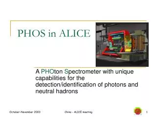
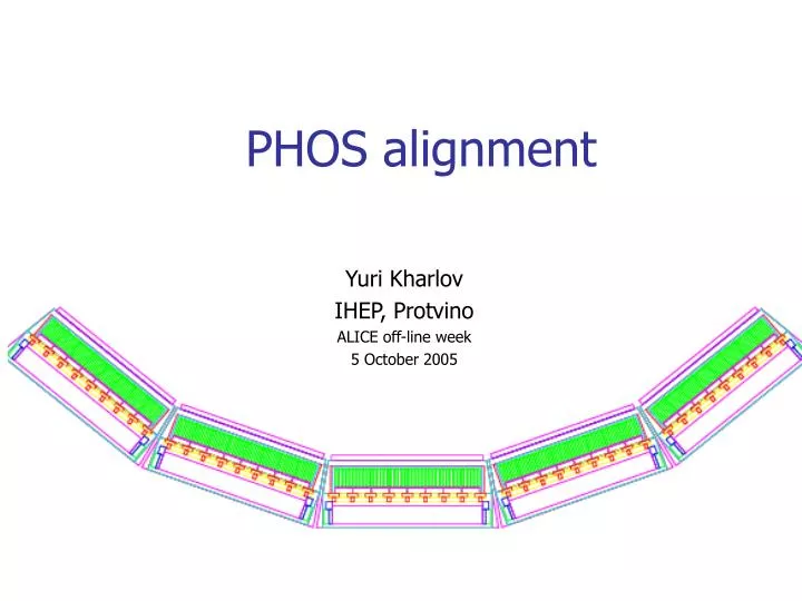
PHOS alignment. Yuri Kharlov IHEP, Protvino ALICE off-line week 5 October 2005. PHOS geometry. PHOS has 5 modules Each module consists of EMC and CPV 1 EMC module contains 3584 crystals 1 CPV module contains 7168 pads. Requirements for alignment. Coordinate resolution of PHOS is 1-2 mm

E N D
PHOS alignment Yuri Kharlov IHEP, Protvino ALICE off-line week 5 October 2005
PHOS geometry PHOS has 5 modules Each module consists of EMC and CPV 1 EMC module contains 3584 crystals 1 CPV module contains 7168 pads PHOS calibration/alignment
Requirements for alignment • Coordinate resolution of PHOS is 1-2 mm • Internal structure of the modules is fixed and not a subject of survey nor alignment: • Crystals are assembled into modules in a hard structure with known position up to few tens of microns • Relative position of CPV and EMC is fixed • Modules are attached to a cradle and may need geometry parameters to store to CDB: • (x,y,z) of the module reference point (center?) in MARS • Rotation matrix of the modules in MARS • For particle identification the track extrapolation from TPC to PHOS is needed. Module position w.r.t. TPC is to be known to a precision not better than 1 mm. • Required precision can be provided by the optical survey which is valid until deinstallation of the detector. PHOS calibration/alignment
Alignment data structure class AliPHOSAlignData protected: Float_tfModuleCenterPosition[5][3]; // xyz position of a module centers in MARS Float_t fModuleAngles[5][3][2]; // Polar and azimuth angles for 3 axes of EMC // modules in MARS public: Float_t GetModuleCenterPosition(Int_t module, Int_t ixyz) Float_t GetModuleOrientation (Int_t module, Int_t ixyz, Int_t iangle) void SetModuleCenterPosition(Int_t module, Int_t ixyz, Float_t pos) void SetModuleAngle (Int_t module, Int_t ixyz, Int_t iangle, Float_t angle) Size of the object: 45 floats PHOS calibration/alignment
Existing geometry implementation in PHOS • Simulation geometry is still ideal and calculated from a minimum set of parameters • All PHOS modules are positioned in ALICE with 3 parameters: • Distance from IP to PHOS front cover (460 cm) • Angle between modules (20 degrees) • Number of modules (5) • Cells of the modules (5664) are produced by division of the modules into elements with fixed size (2.26 cm) • All other parameters are calculated from 3 basic ones: • Position azimuth angle of individual modules (-40, -20, 0, 20, 40) • (x,y,z) for individual module position in MARS • Rotation matrix (AliModule::AliMatrix()) of module orientation in MARS (1, 1, 2, 2, 3, 3) • Normal to the modules point strictly to IP, i.e. 1=0, 2=0, 2=0, 3,=90 • All transformations from global to local system and vice versa are reduced to rotation around z-axis PHOS calibration/alignment
Changes towards real geometry • AliPHOSGetter: to add AlignData() to retrieve AliPHOSAlignData from CDB • AliPHOSGeometry: to add a new data member AliPHOSAlignData *fAlignData • In AliPHOSGeometry::Init() modify to retrieve fAlignData from CDB via AliPHOSGetter::AlignData() • Calculate position coordinates (x,y,z) and orientation angles (1, 1, 2, 2, 3, 3) of individual modules • Modify AliPHOSGeometry::GetGlobal() to calculate rec.point position in MARS with real rotation matrices • Modify AliPHOSGeometry::Global2Local() to transform the point position in MARS into local system of module PHOS calibration/alignment
Conclusion • PHOS alignment is rather simple and reduced to 45 parameters. • Optical survey is enough to provide the necessary precision • Container class with alignment data is ready • Alignment data will be retrieved from CDB similar to calibration data (see Boris’ talk yesterday) • Changes in PHOS geometry are localized to about 5 functions and should be done ASAP PHOS calibration/alignment