Download
1 / 25
250 likes | 462 Views
PHOS Electronics. Overview of presentation Major milestones reached 2004 PHOS electronics, architecture and connectivity, an updated overview Cooling of electronics PHOS Trigger Some results from beam test 2004 Collaboration with China and Japan

E N D
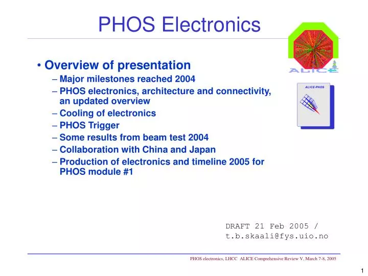
PHOS Electronics • Overview of presentation • Major milestones reached 2004 • PHOS electronics, architecture and connectivity, an updated overview • Cooling of electronics • PHOS Trigger • Some results from beam test 2004 • Collaboration with China and Japan • Production of electronics and timeline 2005 for PHOS module #1 DRAFT 21 Feb 2005 / t.b.skaali@fys.uio.no
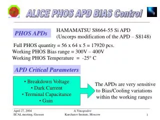
Major milestones reached 2004/05 • Successful test and verification of integrated FEE board for 32 PWO crystals • Dual gain shaper for PHOS dynamic range up to 100 GeV • Digitizaton by ALTRO chip • DCS control of APD bias • 112 boards per PHOS module • Full readout chain to ALICE DAQ system implemented • TPC RCU with DCS mezzanine • ALICE optical data link • DATE DAQ system DCS control of individual APD bias setting
Trigger/Router (TRU) domain connectivity PWO crystals The electronics for one PHOS module comprises 112 FEE boards, grouped into 8 Trigger/Router domains read out by 4 Readout Controller Units. T-card FEE board
FEE board - prototype 2004 Picture shows the setup for the lab and beam tests 2004. In the PHOS module the boards will be mounted from below, with cabling and interconnections at the bottom
Readout Controller Unit - RCU PHOS uses the TPC RCU. Photo shows RCU prototype and setup for beam tests Aug/Oct 2004. The new RCU will be available from spring 2005. 1: DCS board with ARM soft-core processor in FPGA, running Linux 2: RCU board 3: SIU board for ALICE DAQ DDL link 4: Backplane for interconnection to FEE boards The blue numbers indicate connectors for interfaces
Figure 3 - Layout of the PHOS modules cooling circuits. Cooling of Electronics • Preamplifiers: located in cooled (-25 °C) PWO crystal volume • Cooling system developed by Sarov • Main electronics: in ”warm” volume, dissipation ~900 watts/module • Common cooling plant for TOF, CPV and PHOS. Cooling agent: water. • Engineering specification TS/CV EDMS No. 520976 v. 3. Status: Approved.
Figure 6 - Connection of the cooling plant with the primary circuits, with the control structures and the sub-detectors. TOF + PHOS cooling plant Figure 4 - Location of the cooling plant. Cooling plant for TOF / CPV / PHOS Ref. Engineering Specification
The PHOS Trigger • The trigger logic is located in the TRU board, which receives quadlets (2x2 summed) fast signals from 7+7 FEE boards – 448 crystals • The TRU also serves as a data stream router between the FEE boards and RCU • Characteristics:
Programmable amplifiers Trigger logic, implementation, work plan 2005 • April: schematics (PHOS CERN) • June: first FPGA code (PHOS CERN) • July: PCB layout and production (HUST, Wuhan) • Aug/Sep: prototype in test (PHOS lab) Production costs for prototype development covered by PHOS INTAS project, around 20 KCHF
PHOS beam tests 2004 with new FEE electronics Participants: Kurchatov, Bergen, Oslo, Protvino, Wuhan, CERN PHOS beam tests in 2004: 3 periods in T10, PS, East Hall (P=0.5-7 GeV/C) 1.) 02-16 June: PWO + pre-amp: TOF time resolution with TDC 2.) 02-30 August:h, p- -> 2γ invariant mass, new shaper protos 3.) 29 Sept.- 14 Oct.: e- shower and offline timing resolution with new FEE electronics
Measurement of G2 time (t) constant Vout(t)=Q * Gain factor * G2(t) t for single channel Distribution of t Very good correspondence with calculated Gamma-2 shaper implementation with analog component tolerances of 1 %
First e- data with new FEE ALTRO digitized pulse shape for shaper High Gain channel. Left / Right: high / low deposited energies. E(e- ) = 2 GeV Coherent ALTRO clock noise on FEE starts after trigger
Noise problem fixed after test beam low gain: 80 MeV .. 80 GeV Noise ~ 1 ADC count High gain: 5 MeV .. 5 GeV Noise << 1 ADC count
Gain distribution uncalibrated Distribution after individual APD bias setting Gain calibration with 1 GeV electrons and individual APD bias setting APD bias control logic Labview control panel
Status of the Japan Participation and progress in Hiroshima Toru Sugitate and Kenta Shigaki for the Hiroshima ALICE/PHOS Group on 21 January, 2005 at CERN Excerpt from the presentation • CSP milestones for the 1st PHOS module • discussed in July ‘04, based on the successful PS and SPS tests in ‘03; no circuit change from ver.2 decouple the test input from signal lines make space around APD soldering holes • sample evaluation in Sept/Oct at CERN • thanks to Iouri Sibiriak • production of ver.3 started on 25 Oct. in Japan • delivered to Hiroshima in late Dec. • 4,500 CSP’s now at CERN
4,500 CSP’s are now at CERN for the 1st PHOS module Japanese 3 institutes’ official participation in ALICE, together with RIKEN Grant proposal submitted for PHOS/TRD in Japan Plan/discussion of the PHOS@RHIC project underway Ready to kick-off the Physics and Tech. WG’s We are looking forward to working for PHOS@RHIC RSN summary and outlook
Collaboration with HUST, Wuhan • Huazhong University of Science and Technology (HUST), Wuhan. • HUST ranks among the top Chinese Universities. • Coupled with local industry for PCB design/production • Very good instrumentation infrastructure • Wuhan ”Optical Valley” electronics/optical technology • PHOS projects 2004/2005: • Design of analog shaper • Layout and production of FEE board • FEE board controller firmware • Pre-production version of FEE board (2005) • Production of 120 FEE boards for PHOS module #1, summer 2005 • Layout and production of TRU prototype • PHOS test lab under construction in Wuhan
Electronics for PHOS module #1 • PHOS milestone: first module fully integrated and operational in 2005 • Electronics: • APDs purchased – 4000 pcs • Preamps delivered (from Japan) – 4500 pcs • T-cards: current production in Japan • FEE board • Prototype #2 to verify modifications, production in Wuhan • Full batch of 120 board, production in Wuhan, delivery July • TRU • Prototype in 2005, however, module can be operated without TRU • RCU with DCS: cf. TPC production • GTL backplane and intermediate cards: production in Oslo • Firmware (board controller) : Wuhan, CERN, Bergen, TPC • DCS firmware/software: Bergen, Germany