Download
1 / 49
630 likes | 1.11k Views
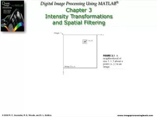
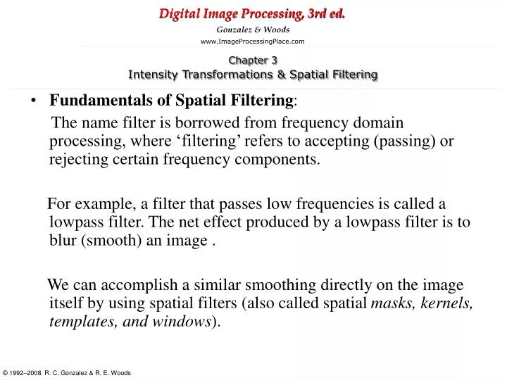
Fundamentals of Spatial Filtering : The name filter is borrowed from frequency domain processing, where ‘filtering’ refers to accepting (passing) or rejecting certain frequency components.

E N D
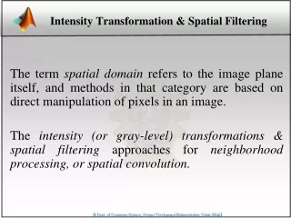
Fundamentals of Spatial Filtering: The name filter is borrowed from frequency domain processing, where ‘filtering’ refers to accepting (passing) or rejecting certain frequency components. For example, a filter that passes low frequencies is called a lowpass filter. The net effect produced by a lowpass filter is to blur (smooth) an image . We can accomplish a similar smoothing directly on the image itself by using spatial filters (also called spatial masks, kernels, templates, and windows).
The MATLAB IPT implements linear spatial filtering using function imfilter which has the following syntax: g=imfilter(f, w, filtering_mode, boundary_options, size_options) where f is the input image, w is the filter mask, g is the filtered result, and the other parameters are summarized in the table; The filtering_mode specifies whether to filter using correlation(‘corr’) or convolution (‘conv’); The boundary_options deal with the border-padding issue, with the size of the border being determined by the size of the filter.
The size_options are either ‘same’ or ‘full’ . ‘full’: The output is of the same size as the extended (padded) image. ‘same’: The output is the same size as the input. This is the default.
g=imfilter (f, w, ‘conv’, ‘replicate’) f=imread(‘squares.tiff’); w=ones(31); gd=imfilter(f,w); imshow(gd, [ ]); Where we used the default boundary option, which pads of the image with 0’s(black). As expected the edges between black and white in the filtered image are blurred.
Non Linear Spatial Filtering: Order-statistic filters are nonlinear spatial filters whose response is based on filters whose response is based on ordering (ranking) the pixels contained in the image area. The best known filter in this category is the median filter, which as its name implies, replace the value of a pixel by median of the intensity values in the neighborhood of that pixel.
Median Filter: Median filters are quite popular because, for certain types of random noise, they provide excellent noise-reduction capabilities with considerably less blurring than linear smoothing filters of similar size. Median filters are particularly effective in the presence of impulsive noise also called salt and pepper noise.
The syntax of function ordfilt2 is; g=ordfilt2(f, order, domain) This function creates the output image g by replacing eachelement of f by the order-th element in the sorted set of neighbor specified by the non zero elements in domain. Here, domain is an mxn matrix of 1s and 0s that specify the pixel locations in the neighborhood that are to be used in the computation. In this sense, domain acts like a mask.
For example, to implement a min filter (order 1) of size mxn use the syntax g=ordfilt2(f, 1, ones(m,n)); In this formulation the 1 denotes the 1st sample in the ordered set of mn samples.
For example, to implement a max filter (100th percentile) of size mxn use the syntax g=ordfilt2(f, m*n, ones(m,n));
The best known order-statistic filter in digital image processing is the median filter, which corresponds to the 50th percentile. g=ordfilt2(f, median(1:m*n), ones(m,n)) Where median(1:m*n) simply computes the median of the ordered sequence 1,2,…,mn.
Sharpening Spatial Filters The principle objective of sharpening is to highlight transformations in intensity. We saw that image blurring could be accomplished in the spatial domain by pixel averaging in a neighborhood. Because averaging is analogous to integration, it is logical to conclude that sharpening can be accomplished by spatial differentiation.
The derivatives of a digital function are defined in terms of differences. First Derivative: must be zero in areas of constant intensity must be non zero at the onset of an intensity step or ramp Must be non zero along ramps Second Derivative: Must be zero in constant areas Must be non zero at the on set and end of an intensity step or ramp Must be zero along ramps of constant slope.
Using Second Derivative for Image Sharpening-The Laplacian We are interested in isotropic filters, whose response is independent of the direction of the discontinuities in the image to which the filter is applied. In other words isotropic filters are rotation invariant, in the sense that rotating the image and then applying the filter gives the same result as applying the filter to the image first and then rotating the result. It can be shown (Rosenfeld and Kak [1982]) that the simplest isotropic derivative operator is the Laplacian, which, for a function(image) f(x,y) of two variables, is defined as
Therefore, it follows from the preceeding three equations that the discrete Laplacian of two variables is
Because the Laplacian is a derivative operator, its use highlights intensity discontinuities in an image and deemphasizes regions with slowly varying intensity levels. This will tend to produce images that have grayish edge lines and other discontinuities, all superimposed on a dark, featureless background. • Shapening effect is obtained by adding the Laplacian image to the original. Where f(x,y) and g(x,y) are the input and sharpened images, respectively. The constant c=-1if the Laplacian filter in Fig3.37.(a) or (b) are used, and c=1 if either of the other two filters is used.
Unsharp Masking and Highboost Filtering Blur the original image Subtract the blured image from the original (the resulting difference is called the mask) Add the mask to the original Letting f ’(x,y) denote the blured image, unsharp masking is expressed in equation form as follows. First obtain the mask: gmask(x,y)=f(x,y)-f ’(x,y) Then we add a weighted portion of the mask back to the original image: g(x,y)=f(x,y)+k* gmask(x,y) When k=1, we have unsharp masking When k>1, the process is referred to as highboost filtering When k<1, de-emphasizes the contribution of the unsharp mask