Download
1 / 17
170 likes | 250 Views
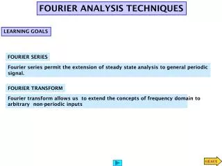
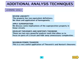
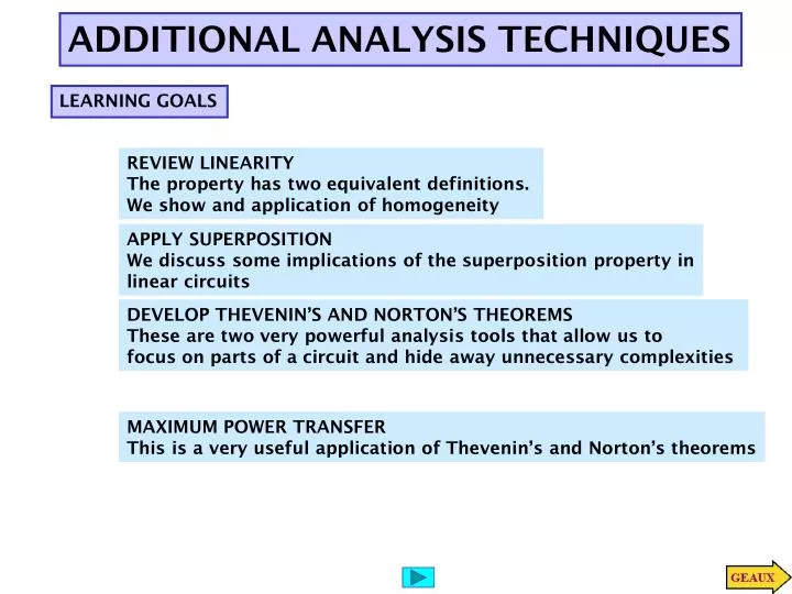
ADDITIONAL ANALYSIS TECHNIQUES. LEARNING GOALS. REVIEW LINEARITY The property has two equivalent definitions. We show and application of homogeneity. APPLY SUPERPOSITION We discuss some implications of the superposition property in linear circuits. DEVELOP THEVENIN’S AND NORTON’S THEOREMS

E N D
ADDITIONAL ANALYSIS TECHNIQUES LEARNING GOALS REVIEW LINEARITY The property has two equivalent definitions. We show and application of homogeneity APPLY SUPERPOSITION We discuss some implications of the superposition property in linear circuits DEVELOP THEVENIN’S AND NORTON’S THEOREMS These are two very powerful analysis tools that allow us to focus on parts of a circuit and hide away unnecessary complexities MAXIMUM POWER TRANSFER This is a very useful application of Thevenin’s and Norton’s theorems
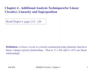
THE METHODS OF NODE AND LOOP ANALYSIS PROVIDE POWERFUL TOOLS TO DETERMINE THE BEHAVIOR OF EVERY COMPONENT IN A CIRCUIT • Thetechniques developed in chapter 2; i.e., combination series/parallel, • voltage divider and current divider are special techniques that are more • efficient than the general methods, but have a limited applicability. • It is to our advantage to keep them in our repertoire and use them when • they are more efficient. In this section we develop additional techniques that simplify the analysis of some circuits. In fact these techniques expand on concepts that we have already introduced: linearity and circuit equivalence
SOME EQUIVALENT CIRCUITS ALREADY USED
USING NODE ANALYSIS FOR RESISTIVE CIRCUITS ONE OBTAINS MODELS OF THE FORM v IS A VECTOR CONTAINING ALL THE NODE VOLTAGES AND f IS A VECTOR DEPENDING ONLY ON THE INDEPENDENT SOURCES. IN FACT THE MODEL CAN BE MADE MORE DETAILED AS FOLLOWS AN ALTERNATIVE, AND EQUIVALENT, DEFINITION OF LINEARITY SPLITS THE SUPERPOSITION PRINCIPLE IN TWO. HERE, A,B, ARE MATRICES AND s IS A VECTOR OF ALL INDEPENDENT SOURCES LINEARITY THE MODELS USED ARE ALL LINEAR. MATHEMATICALLY THIS IMPLIES THAT THEY SATISFY THE PRINCIPLE OF SUPERPOSITION FOR CIRCUIT ANALYSIS WE CAN USE THE LINEARITY ASSUMPTION TO DEVELOP SPECIAL ANALYSIS TECHNIQUES FIRST WE REVIEW THE TECHNIQUES CURRENTLY AVAILABLE NOTICE THAT, TECHNICALLY, LINEARITY CAN NEVER BE VERIFIED EMPIRICALLY ON A SYSTEM. BUT IT COULD BE DISPROVED BY A SINGLE COUNTER EXAMPLE. IT CAN BE VERIFIED MATHEMATICALLY FOR THE MODELS USED.
Redrawing the circuit may help us in recognizing special cases SOLUTION TECHNIQUES AVAILABLE?? A CASE STUDY TO REVIEW PAST TECHNIQUES
The procedure can be made entirely algorithmic 3. Use linearity. 4. The given value of the source (V_s) corresponds to Hence the desired output value is USING HOMOGENEITY 1. Give to Vo any arbitrary value (e.g., V’o =1 ) 2. Compute the resulting source value and call it V’_s Assume that the answer is known. Can we Compute the input in a very easy way ?!! If Vo is given then V1 can be computed using an inverse voltage divider. This is a nice little tool for special problems. Normally when there is only one source and when in our judgement solving the problem backwards is actually easier … And Vs using a second voltage divider Solve now for the variable Vo
NOW USE HOMOGENEITY SOLVE USING HOMOGENEITY
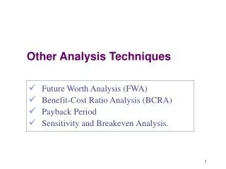
Source Superposition This technique is a direct application of linearity. It is normally useful when the circuit has only a few sources.
Due to Linearity Can be computed by setting the current source to zero and solving the circuit Can be computed by setting the voltage source to zero and solving the circuit FOR CLARITY WE SHOW A CIRCUIT WITH ONLY TWO SOURCES
Circuit with voltage source set to zero (SHORT CIRCUITED) SOURCE SUPERPOSITION = Circuit with current source set to zero(OPEN) Due to the linearity of the models we must have Principle of Source Superposition + The approach will be useful if solving the two circuits is simpler, or more convenient, than solving a circuit with two sources We can have any combination of sources. And we can partition any way we find convenient
Loop equations Contribution of v1 Contribution of v2 LEARNING EXAMPLE WE WISH TO COMPUTE THE CURRENT = + Once we know the “partial circuits” we need to be able to solve them in an efficient manner
We set to zero the voltage source Current division Ohm’s law Now we set to zero the current source Voltage Divider LEARNING EXAMPLE
LEARNING EXAMPLE Set to zero voltage source The current I2 can be obtained using a current divider and V”o using Ohm’s law WHEN IN DOUBT… REDRAW! We must be able to solve each circuit in a very efficient manner!!! If V1 is known then V’o is obtained using a voltage divider V1 can be obtained by series parallel reduction and divider Set to zero current source
Current divider Using source superposition Sample Problem 1. Consider only the voltage source 2. Consider only the 3mA source 3. Consider only the 4mA source
2 1 2 3 1 3 Linearity