Download
1 / 5
50 likes | 59 Views
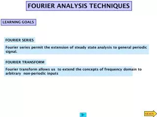
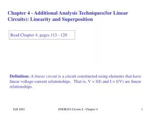
ADDITIONAL ANALYSIS TECHNIQUES. LEARNING GOALS. APPLY SUPERPOSITION We discuss some implications of the superposition property in linear circuits. DEVELOP THEVENIN’S AND NORTON’S THEOREMS These are two very powerful analysis tools that allow us to

E N D
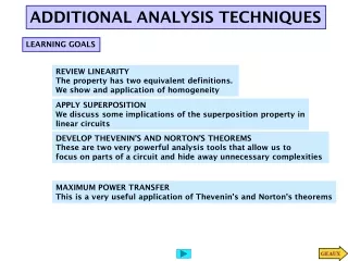
ADDITIONAL ANALYSIS TECHNIQUES LEARNING GOALS APPLY SUPERPOSITION We discuss some implications of the superposition property in linear circuits DEVELOP THEVENIN’S AND NORTON’S THEOREMS These are two very powerful analysis tools that allow us to focus on parts of a circuit and hide away unnecessary complexities
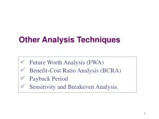
THE METHODS OF NODE AND LOOP ANALYSIS PROVIDE POWERFUL TOOLS TO DETERMINE THE BEHAVIOR OF EVERY COMPONENT IN A CIRCUIT In this section we develop additional techniques that simplify the analysis of some circuits.
Source Superposition This technique is a direct application of linearity. It is normally useful when the circuit has only a few sources.
We set to zero the voltage source Current division Ohm’s law Now we set to zero the current source Voltage Divider LEARNING EXAMPLE
LEARNING EXAMPLE Set to zero voltage source The current I2 can be obtained using a current divider and V”o using Ohm’s law WHEN IN DOUBT… REDRAW! We must be able to solve each circuit in a very efficient manner!!! If V1 is known then V’o is obtained using a voltage divider V1 can be obtained by series parallel reduction and divider Set to zero current source