Download
1 / 16
160 likes | 236 Views
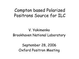
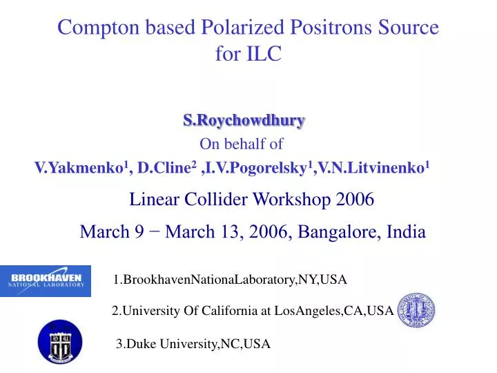
Compton based Polarized Positrons Source for ILC. S.Roychowdhury On behalf of V.Yakmenko 1 , D.Cline 2 ,I.V.Pogorelsky 1 ,V.N.Litvinenko 1. Linear Collider Workshop 2006 March 9 − March 13, 2006, Bangalore, India. 1.BrookhavenNationaLaboratory,NY,USA.

E N D
Compton based Polarized Positrons Source for ILC S.Roychowdhury On behalf of V.Yakmenko1, D.Cline2 ,I.V.Pogorelsky1,V.N.Litvinenko1 Linear Collider Workshop 2006 March 9 − March 13, 2006, Bangalore, India 1.BrookhavenNationaLaboratory,NY,USA 2.University Of California at LosAngeles,CA,USA 3.Duke University,NC,USA
Outline • Review • Requirements (positron beam)for International Linear Collider • Proposal by Omori,et al • ATF(BNL,NY) proposal • Introduce the proposal • Discuss parameter choice • Ring vs. Linac and stacking vs.no-stacking • Laser System • Experiment • ATF,BNL • KEK,Japan • Conclusions
ILC Source Requirements *Length of bunch train=2820x300(ns)=0.85ms~250km **Conversion/capture efficiency for polarized gamma polarized e+ 60% 1.5%
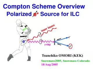
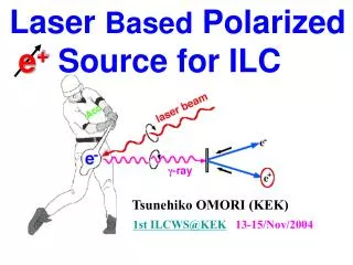
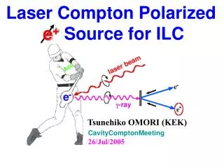
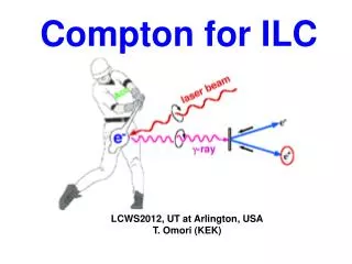
Polarized Positron Production Compton Ring Scheme: CO2 Version (Omori, et al.)
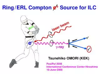
~2 m g to e+ conv. target 80MeV g beam 6GeV 4A e- beam 40MeV e+ beam Polarized Positrons Source (PPS for ILC) • ATF,BNL Proposal • Polarized Gamma Ray Generated By • Compton scattering inside optical cavity of CO2 laser with • 6 GeV electron beam produced by Linac • Expected Efficiency Ng/Ne-~10 • Polarized Positron Beam Generated By • Scattering 80 MeV g ray on a thin target • Capture Efficiency Ne+ / Ng ~1.5%
Merits of the Proposal • Required intensities of polarized positrons obtained because • e-beam charge is sufficiently high(10 times compared to conventional non polarized source) • complex CO2 laser system • L-band type photo injector and linac for acceleration • No R&D required • Laser system • commercially available lasers • R&D for the new mode of operation (described later)
Choice of Parameters Ne # of electrons, Nf# of laser photons Ng # of gamma rays, S area of interacting beams sc Compton cross section • To produce 1012 positrons per bunch ~10 nc electron bunches • Pulse train structure(2820) is set by main linac. • Bunch spacing(~300 ns) is to be changed in the damping ring(any design) • ~3ns spacing matches inversion life time of laser (3ns*2820=8.5microsec) • Laser Energy limited to ~1J • Non linear effects in Compton scattering • Laser Focus @40mm • Practical consideration of e and laser beam focusing • 5 ps long laser • Reducing charge in bunches(positron stacking) leads to • increase in average laser power • Gamma beam size is smaller(compared to other designs) • compact design of Compton backscattering region • Conversion Efficiency (polarized gamma to captured polarized positron) • assumed ~1.5% • subject to optimization
6 GeV Compton Ring rms energy spread ~ 2% CO2 laser interaction with 4MW synchrotron radiation. Dificult ring design Very difficult laser design high repition rate high average power cavity stacking Aperture Requirements of Ring Design small angle Compton back scattering less efficient Linac Design Head On Compton back scattering Ring Or Linac?
No Stacking High current in macro-pulse(~ 4 A) short accelerator sections, more klystrons longer linac Stacking High repitition average beam power inc 3MW for 150Hz. Linac SuperConducting NormalConducting Stacking or No Stacking? • Simpler damping ring and laser system at 5Hz for the scheme without accumulation • may offset linac complexity.
Kerr generator 8 x 200ps CO2 oscillator Laser System Ge optical switch 1x150ns 8 x 5ps 1mJ Yag beam(train of 8bunches 3 ns apart) Regenerative amplifier PC TFP TFP PC amplifier 8x300mJ 8x30mJ BS 8x 30mJ 5ps 1.CO2 oscillator pulse ~100ns Sliced with a Yag pulse train 2. CO2 laser train seeded inside regenerative amplifier cavity round trip 24ns(3*8) 3.Amplified pulses aredumped from cavity(pockels cell) 4.Split into 10 beams 5.After Amplification(~1J) each 8 pulse train ring cavity amplifier amplifier 8 x 1J 8 x 1J 5ps 24ns ring cavities (8 pulses x 3ns spacing) 1J / pulse sustained for 8.5 ms amplifier amplifier IP#1 IP#10
Status Of Laser System For Polarized Positron Source • Optical slicing and amplification • demonstrated at ATF • routine for user experiments* • CO2 oscillator and amplifier • commercially available from SDI • rep rate up to 500Hz • Final Intra-cavity amplifiers • average power 10-20 Kw(150Hz) • Needs R&D • Optical elements • need to withstand high intra-cavity power • to be addressed by industry
Laser From SDIhttp://www.lightmachinery.com/SDI-CO2-lasers.html
Compton Experiment at ATF,Brookhaven(record number of X-rays with 10 mm laser) • X rays generated > ~108 PR ST 2000 • Nx/Ne ~0.1 • Interaction point with high power laser focus of ~30mm was tested. • Nonlinear limit (more then one laser photon scattered from electron) was verified. PRL 2005. Real CCD images Nonlinear and linear x-rays
Compton Experiment at KEK ATF(polarized positrons with 532 nm laser) • Demonstrated beam of 106 polarized -rays (PRL 91/16, 2003) • Demonstrated 104 positron beam with 79% polarization level (KEK Preprint 2005-56, PRL 2005)
Conclusion • We propose a Polarized Positron Source. • based on Compton back scattering inside optical cavity of CO2 laser beam and 6 GeV e-beam produced by linac. • The proposal utilizes commercially available units for laser and accelerator systems. • The proposal requires high power picosecond CO2 laser mode of operation developed at ATF • 3 year laser R&D is needed to verify laser operation in the non standard regime.