Download
1 / 12
120 likes | 211 Views
Compton based Polarized Positrons Source for ILC. V. Yakimenko Brookhaven National Laboratory September 28, 2006 Oxford Positron Meeting. ILC Source requirements. * The length of the bunch train in ILC is 2820x300ns = 0.85 ms or 250 km. Bunch spacing has to be reduced in the dumping ring.

E N D
Compton based Polarized Positrons Source for ILC V. Yakimenko Brookhaven National Laboratory September 28, 2006 Oxford Positron Meeting
ILC Source requirements * The length of the bunch train in ILC is 2820x300ns = 0.85 ms or 250 km. Bunch spacing has to be reduced in the dumping ring. ** Polarization level defines conversion/capture efficiency of polarized g rays into polarized positrons. 60% level corresponds to ~1.5% efficiency.
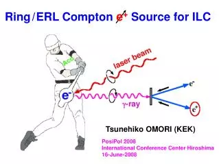
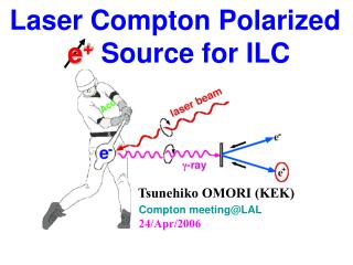
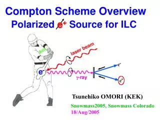
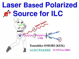
Polarized Positrons Source (PPS for ILC) Conventional Non-Polarized Positrons: In this proposal • Polarized g-ray beam is generated in the Compton back scattering inside optical cavity of CO2 laser beam and 4-6 GeV e-beam produced by linac. • The required intensities of polarized positrons are obtained due to 5 times increase of the e-beam charge (compared to non polarized case) and 10IP CO2 laser system. • Laser system relies on the commercially available lasers but need R&D for the new mode of operation • 5ps 10J@0.05 Hz CO2 laser is operated at Brookhaven ATF.
Compton Experiment at Brookhaven ATF(record number of X-rays with 10 mm laser) • More then 108 of x-rays per pulsewere generated in the experiment PR ST 2000. NX/Ne-~0.1. • (0.35 as of April 2006- limited by laser/electron beams diagnostics) • Interaction point with high power laser focus of ~30mm was tested. • Nonlinear limit (more then one laser photon scattered from electron) was verified. PRL 2005. Real CCD images Nonlinear and linear x-rays
Compton based PPS with CO2 laser • No positron accumulation is needed: • Efficient head-on collision due to higher divergence of CO2 beam. • 10 mm CO2 beam has 10x number of photons per laser energy. • 750 W average power industrial laser. • Easier target and efficient positron capture: • Beam format changed in the injector from 3000 bunches @5 Hz to 100 bunches @150 Hz (1ms @150 Hz is more natural for warm RF and laser). • 40MV/m gradient in post target linac is possible. • Efficient collimation due to strong energy / divergence correlation of the gamma beam in the Compton scattering. • Doable laser: • Commercially available components (designed for 750W@500Hz; needed 750W@150Hz). • Low repetition rate model (10Hz) is operational at ATF as an amplifier of 5ps beam (laser cavity mode with 5ps pulse is needed). • Can be add-on option for non-polarized linac source. • Two Step R&D is needed: • Optimize conversion target and capture for this scheme. Test of the laser cavity at low repetition rate with ATF laser. • Assemble and test seed system and one laser cavity at full power.
Choice of parameters Ng ,Ne and Nfare the numbers of g-rays, electrons and laser photons, S is the area of the interacting beams and sC is the Compton cross sections • ~40 mm laser focus is set by practical considerations of electron and laser beams focusing and requires ~5 ps long laser pulses • Nonlinear effects in Compton back scattering limit laser energy at ~2J • Pulse train structure of 2820 bunches @ 5 Hz is set by main linac. We change it to 100 bunches at 150Hz. This mode is more natural for warm RF and lasers. • ~300ns bunch spacing in the main linac will be changed in the dumping ring in any design. 6-12 ns bunch spacing is selected for optimal current in the drive linac and to match the inversion life time of the laser 12ns *100 bunches = 1.2 ms. • Train of ~10 nC electron bunches is required to produce 1012 polarized gammas per bunch. (~1 g-ray per 1 electron per laser IP) • Conversion efficiency of polarized gammas into captured polarized positrons is assumed at ~1.5% and is subject of optimization.
Kerr generator 2 x 200ps CO2 oscillator Laser system for PPS 1x150ns Ge optical switch 2 x 5ps 1mJ 2 pulses, 5ps, 10mJ (YAG laser) Regenerative amplifier PC TFP TFP 2x5ps 10mJ PC amplifier 2x300mJ BS 2x30mJ 2x 30mJ 5ps • Train of 2 pulses spaced by 12 ns and 5 ps long sliced with a YAG beam from a 150 ns CO2 oscillator pulse • This train is seeded inside a regenerative amplifier cavity that has a round-trip time (12ns x 2=24 ns) • Amplified 2 pulses are dumped from the regenerative cavity with a Pockels cell and, after amplification, split with partial reflectors in 10 beams. • After amplification to 1 J/pulse, each 2-pulse train is injected into a ring cavity individual for each IP • An intracavity amplifier serves just to compensate optical losses during 1.2 s time interval needed for interactions with 100 electron bunches. amplifier amplifier 2 x 1J 5ps 2 x 1J 24ns ring cavities (2 pulses x 12ns spacing) 1J / pulse sustained for 1.2 ms amplifier amplifier IP#1 IP#10
Laser system for PPS • Optical slicing and amplification of 5 ps CO2 pulses has been demonstrated and utilized in routine ATF operation for user experiments. • CO2 oscillator and initial amplifiers are commercially available lasers from SDI and operate at rep. rate up to 500Hz. • Final intra-cavity amplifiers shall operate at average power 750W (100 bunches x 1J x ~5% roundtrip intra-cavity loss x 150Hz). • High pressure CO2 laser is available at 750W average power at 500Hz. • Isotope mixture option is currently considered by the SDI to increase extracted energy. • R&D subjects: • Roundtrip intra-cavity loss optimization • Injection and stabilization energy during 1.2 ms • Operation of laser in nonstandard regime at high rep. rate
Issues (uncertain items) • 1.5% gto e+conversion efficiency: • Assumed from previous JLC/NLC Compton design. Might change number of laser IPs. • Injection/intensity stabilization: • Ge switch is tested at low rep rate only. Cooling and high power 1mm laser/electron beam to control switch might be needed • Laser cavity: • Extensive intra-cavity loss would lead to insufficient laser energy. Amplifier with isotopic mixture or optical pumping might be needed. • Alignment of 10 laser IPs with 40 mm electron beam is doable engineering task that requires testing. • Compton photons in visible (large angles) are valuable diagnostic for feedback (From ATF experiment.)
Conclusion • We propose Polarized Positron Source based on Compton back scattering inside optical cavity of CO2 laser beam and 4-6 GeV e-beam produced by linac. • The proposal utilizes commercially available units for laser and accelerator systems. • The proposal requires high power picosecond CO2 laser mode of operation developed at ATF.
R&D at ATF with LDRD support • We will use existing equipment and attempt to demonstrate 100-pulse intra-cavity train. • Output from our regen will be sent into preamplifier arranged into Compton configuration. • We will need to solve a problem of self-lasing using saturable absorber cell. • The most of tests can be done with 200 ps pulses. • We may try finally 5 ps with isotopes. (Botha at SDI operated with isotopes and did not see a problem with it. ) • This, together with simulations of the train regime, will be the postdoc job. • Our announcement of postdoc position will be in November issue of Laser Focus.
R&D without support • We will buy high-repetition (150 Hz) lasers, add laser room space, • build optical transport, and demonstrate one operational IP. • We are not sure about a real Compton with e-beam at ATF. It does not have sense for several reasons: • difficulty to place amplifier with the cavity in experimental hall • e-beam does not have necessary repetition rate • e-beam does not have right energy to test sequential IP’s (divergence is too high) • single-pulse interaction has been tested sufficiently