Download
1 / 47
470 likes | 626 Views
Compton Scheme Overview Polarized e + Source for ILC. Tsunehiko OMORI (KEK). Snowmass2005, Snowmass Colorado 18/Aug/2005. Why Compton Scheme?. i) Positron Polarization. ii) Full energy/intensity e - beam is NOT necessary to produce positrons. Therefore, Electron and positron

E N D
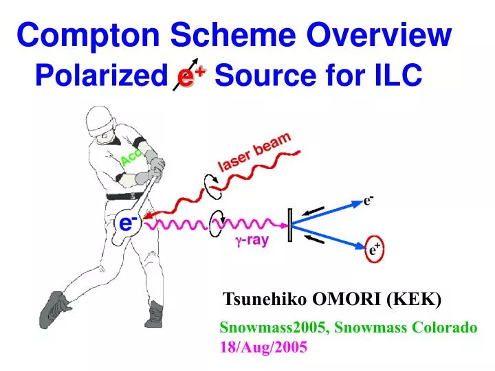
Compton Scheme Overview Polarized e+ Source for ILC Tsunehiko OMORI (KEK) Snowmass2005, Snowmass Colorado 18/Aug/2005
Why Compton Scheme? i) Positron Polarization. ii) Full energy/intensity e- beam is NOT necessary to produce positrons. Therefore, Electron and positron systems remain independent. Easier development, easier commissioning, easier operation. iii) No problem of low energy operation of the collider (GigaZ).
Today’s talk Experiment at KEK-ATF proof-of-principle 2. Concept of Compton Polarized e+ Source for ILC
Experiment at KEK-ATF ATF: Accelerator Test Facility for ILC built at KEK Collaborating institute: Waseda, TMU, KEK, NIRS, and AIST T. Omori, M. Fukuda, T. Hirose, Y. Kurihara, R. Kuroda, M. Nomura, A. Ohashi, T. Okugi, K. Sakaue, T. Saito, J. Urakawa, M. Washio, and I . Yamazaki 120 m
Experiment@KEK i) proof-of-principle demonstration ii) accumulate technical informations: polarimetry, beam diagnosis, …
g-rayMeasured Asymmetry (3 years ago) A= -0.93± 0.15 % A= 1.18± 0.15 % laser pol. = - 79 % laser pol. = + 79 % M. Fukuda et al., PRL 91(2003)164801
Ng(design) = 1 x 10⁷/bunch 2.2 x 10⁷/bunch (achieved) Ne+(design) = 3 x 10⁴/bunch Pol(expected) = 80% Asym (expected) = 0.95%
Measure e+ polarization : use Bremsstrahlung g-ray g-ray polarized e+ E = 40 MeV Pb conveter calculation
Measurement and Cross-Check Measurement e+ beam pol. (laser pol) e- spin in iron (magnet pol.) expected value (MC) ) Calculate A R A(R) : A(R) ~ + 0.95 % ) Calculate A A(L) : A(L) ~ - 0.95 % L ) Calculate A 0 non (Liner) A(0) : A(0) = 0 Cross-Check e+ beam pol. magnet pol. ) Calculate A A(P) : A(P) ~ + 0.95 % P ) N A(N) : A(N) ~ - 0.95 % Calculate A Zero magnet current Not Equal No-polarization, due to residual magnetism
e+ polarization (e+ run): results Measurement e+ beam pol. (laser pol) e- spin in iron (magnet pol.) ) R A(R)= +0.60 ± 0.25% ) L A(L)= -1.18 ± 0.27% ) non (Liner) A(0)= -0.02 ± 0.25% 0 Cross-Check e+ beam pol. magnet pol. ) P A(P)= +0.81 ± 0.26% ) A(N)= -0.97 ± 0.26% N
e+ polarization (e+ run) T. Omori et al., arXiv:hep-ex/0508026 KEK Preprint 2005-56 e+ beam spin e- spin in Iron A(R)= +0.60 ± 0.25% e+ beam spin e- spin in Iron A(L)= -1.18 ± 0.27% e+ beam spin non e- spin in Iron A(0)= -0.02 ± 0.25%
We did e- run, also. e- run e+ run
e-polarization (e- run): results Measurement e- beam pol. (laser pol) e- spin in iron (magnet pol.) ) R A(R)= +0.78 ± 0.27% ) L A(L)= -0.97 ± 0.27% ) non (Liner) 0 A(0)= -0.23 ± 0.27% Cross-Check e- beam pol. magnet pol. ) P A(P)= +0.72 ± 0.27% ) A(N)= -1.03 ± 0.27% N
e- polarization (e- run) e- beam spin e- spin in Iron A(R)= +0.78 ± 0.27% e- beam spin e- spin in Iron A(L)= -0.97 ± 0.27% e- beam spin non e- spin in Iron A(0)= -0.23 ± 0.27%
Summary of Experiment 1) The experiment was successful. High intensity short pulse polarized e+ beam was firstly produced. Pol. ~ 80% 2) We confirmedpropagation of the polarization from laser photons -> g-rays -> and pair created e+s & e-s. 3) We established polarimetry of short pulse & high intensity g-rays, positrons, and electrons.
Concept of Compton polarized e+ source for ILC Collaborating Institutes: BINP, CERN, DESY, Hiroshima, IHEP, IPN, KEK, Kyoto, LAL, NIRS, NSC-KIPT, SHI, and Waseda SakaeArakiYasuoHigashiYousukeHondaMasaoKurikiToshiyukiOkugi TsunehikoOmoriTakashiTaniguchiNobuhiroTerunuma, JunjiUrakawaXArtruMChevallier, VStrakhovenko, EugeneBulyakPeterGladkikhKlausMeonig, RobertChehabAlessandroVariola FabianZomerFrankZimmermann, KazuyukiSakaueTachishigeHiroseMasakazuWashioNoboruSasaoHirokazuYokoyamaMasafumiFukuda KoichiroHiranoMikioTakanoTohruTakahashiHirokiSatoAkiraTsunemiand JieGao
We had a conceptual design for a warm LC. ~ 100 bunches in ~ 300 nsec, bunch to bunch : ~2.8 nsec, 1.2x10¹⁰ positrons/bunch, pol. ~ 54%. T. Omori et al., NIM A500 (2003) 232-252
Conceptual Design for warm LC Ne+=1.2x10¹⁰/bunch Ne+/Ng=1.4% T. Omori et al., NIM A500 (2003) 232-252
Is Compton applicable to a cold LC? Yes ! With New and Improved design Full use of slow repetition rate (5Hz)
ILC requirements 2x10¹⁰ e+/bunch (hard) 2800 bunches/train (hard) 5 Hz (we have time to store e+s) Strategy Old: Design for warm LC make positrons at once. both electron & laser beams : single path T. Omori et al., NIM A500 (2003) 232-252 New: Design for cold LC (ILC) make positrons in 100 m sec. Electron storage ring, laser pulse stacking cavity : Re-use !!! positron stacking in DR. Basic Idea: K. Moenig P. Rainer
Re-use Concept laser pulse stacking cavities Compton ring positron stacking in main DR Electron storage ring to main linac
Two versions CO2 YAG Electron Beam (Compton Ring) Electron Energy (GeV) 4.1 1.3 Ne-/bunch 6.3x10¹⁰ 6.3x10¹⁰ Spot Size at CP (micron) 5(h)x25(v) 5(h)x25(v) Circumferences (m) 649.4 276.7 Number of Bunches 280x2 280 Number of Trains 2 1 Laser Beam Photon Energy (eV) 0.117 1.16 Pulse Energy/bunch(mJ) 210 590 Spot Size at CP (micron) 25(h)x25(v) 5(h)x5(v) Gamma-rays Energy(MeV) 23-29 23-29
Two versions CO2 YAG Electron Beam (Compton Ring) Electron Energy (GeV) 4.1 1.3 Ne-/bunch 6.3x10¹⁰ 6.3x10¹⁰ Spot Size at CP (micron) 5(h)x25(v) 5(h)x25(v) Circumferences (m) 649.4 276.7 Number of Bunches 280x2 280 Number of Trains 2 1 Laser Beam Photon Energy (eV) 0.117 1.16 Pulse Energy/bunch(mJ) 210 590 Spot Size at CP (micron) 25(h)x25(v) 5(h)x5(v) Gamma-rays Energy(MeV) 23-29 23-29
CO2 Pros: large Nphoton (Nphoton = Elaser/Ephoton) Larger tolerance Cons: Higher e- beam energy --> More Cost No experience of laser pulse stacking of CO2 YAG Pros: Low e- beam energy --> Less Cost Experience of laser pulse stacking of YAG Cons: Smaller Nphoton (Nphoton = Elaser/Ephoton) Small tolerance
325 MHz 325 MHz 325 MHz Laser Pulse Stacking Cavity Input laser (CO2 laser) Energy 2.1 mJ/bunch 3.077 nsec bunch spacing train length = 110 msec Laser-electron 8 degree crossing Laser pulse in cavity (CO2) 210 mJ/bunch single bunch in a cavity Cavity Enhancement Factor = 100
Compton Ring (e- storage Ring) Loss of Electrons by collision Negligible Ng/collision decrease due to bunch lengthening Pulsed mode operation Laser on ~ 100 micro sec Laser off ~ 9.9 m sec (for cooling) Repeat 100 Hz
2.0 1.6 1.2 0.8 0.4 1.6 1.2 0.8 0.4 CO2 ring YAG ring Ng/electron/turn (in all energy of g-ray) 0 10 20 30 40 50 Turns 0 20 40 60 80 100 Turns Compton Ring (e- storage Ring) Average Ng/turn (in 23-29 MeV) CO2 : 1.78x10¹⁰ /turn YAG : 1.36x10¹⁰ /turn (average in 50 turns) (average in 100 turns)
Schematic View of Whole System (CO2) This part is necessary for any scheme.
Positron Acceleration to DR Pre Positron Accelerator (PPA) Accelerate up to 287 MeV Normal conducting L-band linac pulse~100 msec, rep. = 100Hz Main Positron Accelerator (MPA) Accelerate up to 5 GeV Two versions are now under considerration i) SC linac L ~ 270 m (rep. = 100Hz) almost identical to main linac need more cooling power/module (x4 of main linac) ii) Normal conducting linac L ~ 620 m (rep. = 100Hz) identical to the latter part of PPA
e+ stacking in Damping Ring Main DR itself is the ideal choice of stacking ring Can store full number of e+ bunches Have short damping time of ~10 m sec Have large longitudinal bucket area ~ 450 mm ~10 x injected beam size : ~ 5mm(rms)x10(edge) Stack in longitudinal phase space We assume Circumference ~3.3 km. RF = 650 MHz (3.077 n sec of bunch-to-bunch) 2800 bunches in a ring (280 bunches/train x 10 trains) (10 turn injection in 110 m sec + 9.9 m sec damping)x10 --> 100 times of stacking in a bucket in total 10 turns of DR <--> 50 turns Compton ring (CO2)
i-th bunch on j-th DR turn -0.03 0.03 dEnergy/Energy e+ in a bucket Time -0.4 0.4 Longitudinal Pos. (m) e+ stacking in Damping Ring (simulation) 1st bnch on 1st trn 5th bnch on 5th trn 10th bnch on 10th trn T=0 ~110 msec before 11th bnch on 941st trn 11th bnch on 942nd trn 15th bnch on 946th trn ~10 msec before 21st bnch on 1882nd trn 20th bnch on 951st trn 100th bnch on 8479th trn ~10 msec + 110 msec ~20 msec ~100 msec + 110 msec 100 bnchs on 9410th trn 100 bnchs on 18820th trn stacking loss = 18% in total ~110 msec ~200 msec
Note DR circumference in this design (~ 3 km) is an example. If DR-people choose other circumference, Compton scheme can be changed to meet it. If ILC choose 5600-bunch, Compton scheme can be changed to meet it. Optimization is still on going. We think that Ne+ can exceeds 2x10¹⁰ in both CO2 and YAG versions. Optimization is still on going. We think that stacking loss can be made much smaller. We are trying to make revised design of CO2 Compton ring, C ~ 600 m --> C ~ 300 m, in order to reduce cost.
Summary of ILC source design Compton scheme is a good candidate of ILC polarized e+ source. We have new Idea make positrons in 100 m sec. Electron storage ring laser pulse stacking cavity positron stacking in main DR 2.0x10¹⁰ e+/bunch x 2800 bunches @ 5Hz with high polarization (~ 60%) (1.6x10¹⁰ e+/bunch in YAG version) Some values are extrapolation from old design. We need detailed simulation.
Summary of Summaries Why Compton scheme? Independent: in operation, in energy, in commissioning, in electron-positron arms, and in development. How R/D is going on? Very healthy in three aspects. i) Proof of principle (experiment): finished Good results of polarization. Establish method of pol. measurement and beam diagnosis. ii) Conceptual Design (simulation) Promising.5 Hz is suitable for Compton iii) Component R/D (experiment) Next speaker (J. Urakawa).