Download
1 / 28
280 likes | 315 Views
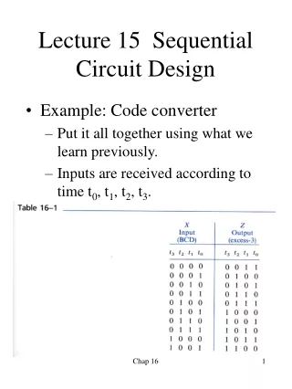
Sequential Circuit Design. State Optimization. Equivalent States: Two states are equivalent if, for each member of the set of inputs, they give exactly the same output and send the circuit either to the same state or to an equivalent state.

E N D
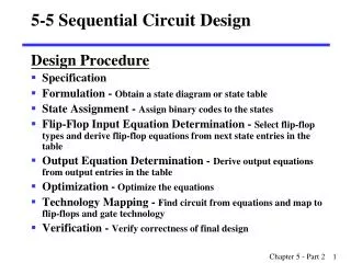
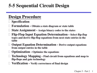
State Optimization • Equivalent States: • Two states are equivalent if, for each member of the set of inputs, • they give exactly the same output and • send the circuit either to the same state or to an equivalent state. • If two states are equivalent, one can be eliminated without effecting the behavior of the FSM.
NS output PS x=0 x=1 x=0 x=1 a a b 0 0 b c d 0 0 c a d 0 0 d e f 0 1 e a f 0 1 f g f 0 1 g a f 0 1 Row Matching Example State Transition Table
NS output PS x=0 x=1 x=0 x=1 a a b 0 0 b c d 0 0 c a d 0 0 d e f 0 1 e a f 0 1 f e f 0 1 NS output PS x=0 x=1 x=0 x=1 a a b 0 0 b c d 0 0 c a d 0 0 d e d 0 1 e a d 0 1 Row Matching Example (cont) Reduced State Transition Diagram
State Optimization Algorithm Implication Chart
State Optimization Algorithm • Implication Chart After First Pass • Processing order is important
State Optimization Algorithm • Implication Chart After Second Pass
Equivalent Sequential Circuits • Definition: • Sequential circuit N1 is equivalent to sequential circuit N2 if • for each state p in N1, there is a state q in N2 such that p≡q , and • conversely, for each state s in N2 , there is a state t in N1 such that s≡t.
State Encoding • The simplest assignment of s coded states to 2n possible states is to use the first s binary integers in binary counting order. • 000, 001, 010, 011, 100 • However, the simplest state assignment does not always lead to the simplest circuit. • In fact, the state assignment often has a major effect on circuit cost (was previously shown). • In general, the only formal way to find the best assignment is to try all the assignments. • That’s too much work!!
Moore Machine OKA0: still OK (because from an OK state, got B=1), and got a 0 on A A0: got 0 on A A1: got 1 on A Reset/0 OKA1: still OK (because from an OK state, got B=1), and got a 1 on A OK00: got 00 on A init 00 OK11: got 11 on A 10 01 11 00/01 10 00 A0 A1 11 01 10 10 11 00 10 00 11 01 00 10 OK11 OK00 01 11 10 00 11 01 11 OKA1 OKA0 01
State Table • OK00 and OKA0 are equivalent • OK11 and OKA1 are equivalent
Moore Machine OKA0: still OK (because from an OK state, got B=1), and got a 0 on A A0: got 0 on A A1: got 1 on A Reset/0 OKA1: still OK (because from an OK state, got B=1), and got a 1 on A OK00: got 00 on A init 00 OK11: got 11 on A 10 01 11 00/01 10 00 A0 A1 11 01 10 11 10 00 11 01 00 10 OK1 11 OK0 11 01
State Encoding • Guidelines: • Choose an initial coded state into which the machine can easily be forced at reset • 00. . . 00 or 11. . . 11 in typical circuits. • Minimize the number of state variables that change on each transition. • Maximize the number of state variables that don’t change in a group of related states • i.e., a group of states in which most of transitions stay in the group.
State Encoding • Samples:
Synthesis Using D FF Present State Output Next State
State Assignment • Unused States: • Each of the m states must be assigned a unique code • Minimum number of bits required is n such thatn ≥ log2 mwhere x is the smallest integer ≥ x • There are 2n - m unused states
State Assignment • Unused States: • Minimal risk: • Assumes that it is possible for the state machine somehow to get into one of the unused (or “illegal”) states, • (due to a hardware failure, an unexpected input). • Therefore, all of the unused state-variable combinations are identified, and explicit next-state entries are made so that, for any input combination, the unused states go to the “initial” state • Minimal cost: • Assumes that the machine will never enter an unused state. • Therefore, in the transition and excitation tables, the next-state entries of the unused states can be marked as “don’t-cares”.
Case 1: Minimal Risk • Assumption: • Unused states go to 000 (minimal risk) D1 = Q1 + Q2¢.Q3¢
Case 1: D2 Equation D2 = Q1.Q3¢.A¢ + Q1.Q3.A + Q1.Q2.B
Case 1: D3 Equation D3 = Q1.A + Q2¢.Q3¢.A
Case 1: Z Equation Z = Q1.Q2.Q3¢ + Q1.Q2.Q3 = Q1.Q2
Case 2: Minimal Cost • Assumption: • next states of unused states are “don’t-cares” (minimal cost). • Z = don’t care for unused states. D1 = 1
Case 2: D2 Equation D2 = Q1.Q3¢.A¢ + Q3.A + Q2.B
Case 2: D3 Equation D3 = A
Case 2: Z Equation Z = Q2