Download
1 / 54
560 likes | 744 Views
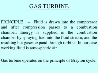
GAS TURBINE FIRE AND EXPLOSION SAFETY. ROGER SANTON RETIRED HM PRINCIPAL SPECIALIST INSPECTOR OF HEALTH AND SAFETY. Size Range. 7 0RDERS OF MAGNITUDE 500+Mw circa one ton fuel / sec 1-10 w circa 0.2g/sec. Size Range. POWER GENERATION 1-1000 mW.

E N D
GAS TURBINE FIRE AND EXPLOSION SAFETY ROGER SANTON RETIRED HM PRINCIPAL SPECIALIST INSPECTOR OF HEALTH AND SAFETY
Size Range • 7 0RDERS OF MAGNITUDE • 500+Mw circa one ton fuel / sec • 1-10 w circa 0.2g/sec
Size Range • POWER GENERATION • 1-1000 mW
POWER GENERATION (SIMPLE OR COMBINED CYCLE) • HAZARDS • INCIDENTS • PRECAUTIONS
HAZARDS • FIRE • EXPLOSION • MECHANICAL • NOISE • ELECTRICAL & ELECTROMAGNETIC • TRAPPINGSee ISO 21789 (ref 1)for guidance on all hazards
FIRE • FUEL FROM LEAK • GT FUEL – NATURAL GAS, OIL, LPG, NAPHTHA, BIOGAS, H2 etc. • LUBE OIL • HYDRAULIC OIL • IGNITION • Hot surface • Mechanical spark • etc.
EXPLOSION • FUEL FROM LEAK • GAS, VAPOUR, LIQUID MIST, as a FLAMMABLE CLOUD • IGNITION • ENCLOSURE (Can be a normal ventilated enclosure or turbine hall)
GAS TURBINE INCIDENTS, UK OFFSHORE AND ONSHORE (ref. 2) YEAR GAS LEAKS FIRES EXPLOSIONS ELECTRICAL CONTROLS OTHER TOTAL FATAL INJURY 1991 4 1 1 1 7 1992 6 4 1 5 16 1993 7 12 1 20 1 1994 14 5 1 2 22 1995 14 3 2 1 2 21 1996 10 7 3 3 3 24 1 1997 7 8 2 2 5 25 1998 8 8 4 22 1999 11 4 2 1 7 24 2000 12 10 3 26 2001 7 9 1 1 2 3 21 3 2 2002 9 3 1 2 17 1 2003 4 1 1 3 9 TOTAL 113 75 13 1 12 40 254 3 5
Incident severity • Minor – very small releases, insignificant consequences, protection adequate • Significant – Potential for injury or major loss, contained or mitigated successfully • Major – Fatality, significant injury, or substantial loss
KLEEN ENERGY • FEB 7TH 2010 • EXPLOSION AT KLEEN ENERGY SYSTEMS POWER STATION, CONNECTICUT, UNDER COMMISSIONING. • “BLOW-DOWN” OF MAIN GAS SUPPLY PIPE • 6 FATALITIES, 50 INJURED • 17 COMPANIES FINED A TOTAL OF $16.6 M BY OSHA OVER 371 SAFETY VIOLATIONS
MITIGATION DESIGN CONSTRUCTION INSTALLATION COMMISSIONING OPERATION MAINTENANCE INSTRUCTIONS TRAINING SUPERVISION
LEAK RISK REDUCTION MINIMUM NUMBER OF JOINTS (ZERO?) DESIGN FOR MOVEMENT, BUT MINIMISE FLEXIBLES DESIGN FOR EASE OF ASSEMBLY, INSPECTION & MAINTENANCE QA ASSEMBLY AND RE-ASSEMBLY PRESSURE TEST, LEAK TEST (ref. 3) ENCAPSULATE JOINTS FLANGE GUARDS (For liquid releases in particular) DOUBLE WALLED PIPE
LEAK DETECTION GAS DETECTION CATALYTIC IR ABSORPTION ACOUSTIC IR – VERY SENSITIVE (ref 4) LIQUID MIST DETECTION (Semi-quantitative) (Test methods - ref. 5)
SOURCES OF IGNITION HOT SURFACE AUTOIGNITION ELECTRICAL GEARBOXES, BEARINGS & FANS FLASHBACK FIRES IN FUEL PIPES PIPEWHIP BLADE AND CONTAINMENT LOSS STATIC ETC., ETC., ETC.,ETC…………………………………….
IGNITION RISK REDUCTION AREA CLASSIFICATION SURFACE TEMPERATURE LIMITATION BY COOLING INSULATION SHIELDING
FIRE DETECTION & SUPPRESSION MINIMUM - RATE COMPENSATED THERMAL DETECTION UV, IR, SMOKE DETECTION AS APPROPRIATE CO2 OR WATER MIST SUPPRESSION ACCESS CONTROL VENTILATION CONTROL SUPPRESSION PERSISTENCE TRIP (maintain rotation and thus lube even if on fire)
MITIGATION OF FIRE & EXPLOSION BY ENCLOSURE DESIGN LEAK RISK REDUCTION LEAK DETECTION IGNITION RISK REDUCTION FIRE DETECTION/SUPPRESSION
MITIGATION - FIRE & EXPLOSION LEAK RISK REDUCTIONLIMITED LEAK TESTING LEAK DETECTIONCLOUD SIZE UNKNOWN IGNITION RISK REDUCTION FIRE DETECTION/SUPPRESSIONRELIABILITY ISSUES BASIS OF SAFETY AGAINST EXPLOSIONS ??
FINITE FORESEEABILITY OF LEAKS AND SOURCES OF IGNITION LEADING TO EXPLOSIONS BASIS OF SAFETY AGAINST EXPLOSIONS – DILUTION VENTILATION (EXPLOSION SUPPRESSION) (EXPLOSION RELIEF)
DILUTION VENTILATION • ..SHOULD QUICKLY AND EFFECTIVELEY DILUTE ANY FORESEEABLE RELEASE TO BELOW THE LEL; THERE SHOULD BE NO STAGNANT REGIONS, OR RECIRCULATION LEADING TO RE-ENTRAINMENT, AND ACCUMULATIONS OF EXPLOSIBLE MIXTURE SHOULD BE MINIMISED TO SAFE LEVELS.
DILUTION VENTILATION • Small enclosures (<50m3) • Smoke • Anemometer • Large enclosures • ???
DILUTION VENTILATION • Small enclosures <50m3) • Smoke • Anemometer • Large enclosures • CFD (ref 10)
CFD required a criterion to discriminate good from bad ventilation. HSE proposal (1996 ref.6) was that the size of the flammable cloud from the largest undetectable gas leak, as defined by the iso-surface at 50% of LEL should be no larger than 0.1% of the net enclosure volume.
Dilution Ventilation Criterion • ISO 21789 – First detailed appearance of dilution ventilation criterion in a standard • 5.17.5 - recommended CFD if surface temperatures exceed AIT of flammable gas, vapour or mist, or where risk assessment indicates a residual risk of ignition • 5.16.5.3.3 – criteria from JIP (ref. 7)
JIP Dilution Ventilation Criterion • Based on CFD and explosion trials • Gas detector in outlet duct, gas leak at trip setting • 100% LEL iso-surface of cloud volume • Converted to equivalent stoichiometric volume • Should be less than 0.1% of net volume of enclosure • Safety factor to be based on risk assessment • Hole size 0.25mm2 to 25 mm2 • Based on 10mbar enclosure strength
Dilution Ventilation Criterion • If enclosure strength can be shown to be 15mbar cloud volume may be 0.15% • CFD ventilation prediction to be verified • Several leak points to be modelled, using CFD to predict poorly ventilated zones
Counter- intuitive • Increased ventilation rate may be regarded as improvement • It has the effect of diluting the gas concentration at the outlet and thus leads to a larger leak to be modelled • Lower ventilation rate, if possible, reduces leak size to be modelled • Distribution of ventilation and avoidance of stagnant zones and re-entrainment are more important
ATEX, DIRECTIVE 94/9/EC ARTICLE 1 "EQUIPMENT MEANS MACHINES...INTENDED FOR THE GENERATION...AND CONVERSION OF ENERGY...WHICH ARE CAPABLE OF CAUSING AN EXPLOSION THROUGH THEIR OWN POTENTIAL SOURCES OF IGNITION." GAS TURBINES ARE INCLUDED IN THIS SCOPE
ATEX, DIRECTIVE 94/9/EC ANNEX II, PARAGRAPH 1.3.1 "POTENTIAL IGNITION SOURCES SUCH AS...HIGH SURFACE TEMPERATURES...AND OTHER IGNITION SOURCES MUST NOT OCCUR.“ IN EFFECT, GAS TURBINES CANNOT OPERATE IN THE ZONED AREAS CREATED BY THEIR OWN FUEL SUPPLIES EuMIGT REPRESENTATIONS TO EC
ATEX 2014/34/EU Guidelinesextracts from para 244 • Gas turbine fuel supplies may give rise to a potentially explosive atmosphere in the vicinity of the turbine. Additionally, other sources of a potentially explosive atmosphere may also exist, e.g. lubricating oils. Equipment in category 3 of equipment-group II would usually be required in such areas. • In normal circumstances, a gas turbine could have hot surfaces above the auto ignition temperature of the fluids used. Operation under fault conditions may increase surface temperatures.
ATEX 2014/34/EU Guidelinesextracts from para 244 • A gas turbine which has surface temperatures that can lead to the ignition of a potentially explosive atmosphere cannot comply with the relevant provisions of Directive 2014/34/EU. In such circumstances additional measures are required. • A number of alternatives are available for selection as a basis for safety, e.g. limitation of the volume of the explosive atmosphere by dilution ventilation , explosion relief, explosion suppression or a combination of these techniques.
AREA CLASSIFICATION • INSIDE DILUTION VENTILATED ENCLOSURE, AREA CLASSIFICATION WAS NOT REQUIRED, (BS 5345,1983; RECOMMENDED BY IP CODE 15, 1990, PM84) BUT ATEX II REQUIRES AREA CLASSIFICATION AND PROTECTED ELECTRICAL EQUIPMENT. • Equipment in category 3 (zone 2) of equipment-group II would usually be required. (ATEX 2014/34/EU Guidelines para 244) • For natural gas see IGEM SR 25 (ref 11)
LIQUIDS • LIQUID FUELS, LUBRICATING AND HYDRAULIC OILS • ATEX and DSEAR SPECIFICALLY APPLY TO MIST EXPLOSION POTENTIAL • RISK REDUCTION, RISK ASSESSMENT • MIST DETECTION • FLANGE GUARDS
LIQUIDS • ATEX and DSEAR SPECIFICALY APPLY TO MIST EXPLOSION POTENTIAL • AREA CLASSIFICATION REQUIRED • KEROSINE AS PROXY FOR ZONE EXTENT IN EI15 (ref. 9) • CFD