Download
1 / 39
420 likes | 654 Views
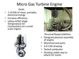
Gas Turbine Plant. Prepared by: Kamil Bin Sahidin. Content. How does it works? Gas Turbine Components Gas Turbine Applications Gas Turbine Performances. How does it works?. :. Gas turbine engines are, theoretically, extremely simple. They have 3 parts:

E N D
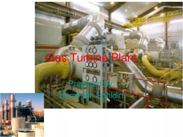
Gas Turbine Plant Prepared by: Kamil Bin Sahidin
Content • How does it works? • Gas Turbine Components • Gas Turbine Applications • Gas Turbine Performances
How does it works? : • Gas turbine engines are, theoretically, extremely simple. They have 3 parts: • A compressor to compress the incoming air to high pressure. • 2. A combustion area to burn the fuel and produce high pressure, high velocity gas. • 3. A turbine to extract the energy from the high pressure, high velocity gas flowing from the combustion chamber.
How does it works? • Compressor Pumps Air into Combustion Chamber • Fuel in Gaseous or Liquid Spray Form Injected into Combustion Chamber and Burned • Continuously Expanding Combustion Products Directed Through Stationary Airfoils − react against the blades of a turbine wheel, causing the shaft to turn, driving the compressor • Remaining High Energy Gas Can be Used − expansion across a nozzle (propulsion) − expansion across another turbine stage (shaft power)
Compressor • Air is drawn into the front of the compressor. Each succeeding stage is smaller increasing velocity (recall Bernoullis equation). • Between each rotating stage is a stationary stage or stator. The stator partially converts the high velocity to pressure and directs the air to the next set of rotating blades. • The rotor imparts velocity to the air (like a fan). Each stage consists of a rotor and stator and results in a pressure increase.
Combustion chamer • Air exits the compressor and enters the diffuser. Suddenly, the air moves from a narrow passage into a wide area. By bernoulli, the air loses velocity and expands in volume and increases pressure. Now, the air is slow moving and high pressure, usually about 19:1. Fuel is injected here and the mixture is ignited by a spark. The spark causes a rapid increase in the volume of the air an combustion gases (at constant pressure). • The combustion mixture goes rearward to a nozzle which directs the gas onto the turbine blades and accelerates the gases. The gases are now high velocity, high temperature, low pressure and are used to turn the turbine. The kinetic and thermal energy of the gases are transferred the turbine blades. The turbine is multistaged to remove as much of the energy from the gas as possible.
Turbine • Hot gases converted to work • Can drive compressor & external load
Advantages of GT • Weight reduction of 70% • Simplicity • Reduced manning requirements • Quicker response time • Faster Acceleration/deceleration • Modular replacement • Less vibrations • More economical
Disadvantages of GT • Many parts under high stress • High pitched noise • Needs large quantities of air • Large quantities of hot exhaust (target) • Cannot be repaired in place
Advantages over Diesel Plant • The work developed per kg of air is large • Less vibration due to perfect balancing • Less space • Capital cost considerably less • Higher mech eff. • Running speed of the turbine large • Lower installation and maintenance cost
POWER UNIT TURBINE ASSEMBLY COMPRESSOR ASSEMBLY TORQUEMETER ASSEMBLY COMBUSTION ASSEMBLY ACCESSORY DRIVE HOUSING ASSEMBLY REDUCTION GEAR ASSEMBLY
Fuel system Left External Fuel Tank Right External Fuel Tank No 2 Fuel Tank No 3 Fuel Tank No 1 Fuel Tank No 4 Fuel Tank Right Auxiliary Fuel Tank Left Auxiliary Fuel Tank
Turbo Jet • In turbo-unit, the turbine of the gas turbine power plant produces just sufficient power to drive the compressor by partial expansion in turbine. • The gases coming out from the turbine,which are higher pressure than atmos are expanded in nozzle and produce a very high velocity jet. • Gives a forward motion to the air craft by jet reaction.
Air craft Exhaust gases from nozzle Direction of air craft 4 3 2 cc 5 c T Exhaust to atmosphere nozzle 1 Air from atm
Heater 2 3 T C 1 4 Cooler Closed cycle GT
Methods for improvement of Thermal Efficiency of Open cycle GT • Intercooling • Reheating • Regeneration
Fuel (heat) Intercooler CC 2’ 5 4’ 3 L.P C H.P C T Work 6’ 1 Exhaust Air in GT with Intercooler
T-s diagram with intercooler • 1-2’ : L.P (low pressure) compression • 2’-3 : Intercooling • 3-4’ : H.P (high pressure) compression • 4’-5 : C.C – heating • 5-6’ : T (turbine) - expansion
Effect of intercooling 1- work input with intercooling is less than the work input with no intercooling. 2- when the compressor work input is reduced then the work ratio is increased. 3- heat supplied when intercooling is used is greater than with no intercooling. 4- although the net work output is increased by intercooling it is found in general that the increase in heat to be supplied causes the thermal efficiency to decrease.
Reheating Reheater CC 1 CC 2 2’ 5 4’ 3 C L.P T H.P T Work 6’ 1 Exhaust Air in
T 3 5 4’ 6’ 2’ 2 4 6 L’ L 1 S
Effect of reheater • The output of GT can be improve by expanding the gases in two stages with a reheater between the two. • The HP turbine drive the compressor and the LP turbine provide useful power output. • Reheating increase the net work output • By reheating the heat to be supplied is also increased, thus the net effect can be to reduce the thermal efficiency.
Regeneration 6 Exhaust Xxxxxxxxxxxxxxxxxxxxxxx xxxxxxxxxxxxxxxxxxxxxx CC 5’ Regenerator 3 4 2’ T C 1
T 4 3 2 2’ 5’ 5 6 1 S
Effect of regeneration • The exhaust gas from a gas turbine carry large quantity of heat with them since the temp. is far above the ambient temp. • They can be used to heat the cc. • Usually used large GT unit s for marine propulsion or industrial power.