Download
1 / 61
1.18k likes | 2.14k Views
GAS TURBINE ENGINE. EXHAUST. TABLE OF CONTENTS. CHAPTER 1 - CONSTRUCTIONAL FEATURES AND PRINCIPLES OF OPERATION S/C: Location S/C: Function CHAPTER 2 - CONVERGENT, DIVERGENT AND VARIABLE AREA NOZZLES CHAPTER 3 - ENGINE NOISE REDUCTION CHAPTER 4 - THRUST REVERSERS S/C: Function

E N D
GAS TURBINE ENGINE EXHAUST 1 October, 2014
TABLE OF CONTENTS CHAPTER 1 - CONSTRUCTIONAL FEATURES AND PRINCIPLES OF OPERATION S/C: Location S/C: Function CHAPTER 2 - CONVERGENT, DIVERGENT AND VARIABLE AREA NOZZLES CHAPTER 3 - ENGINE NOISE REDUCTION CHAPTER 4 - THRUST REVERSERS S/C: Function S/C: Location S/C: Principle S/C: Turbo-propellers 1 October, 2014
Location • In a single flow turbojet, the exhaust duct is an element located within the engine behind the turbine and by which the gas stream, having undergone the engine thermodynamic cycle, is ejected • In the case of a dual-flow turbojet, the hot flow exhaust duct is positioned on the turbine outlet as on a single flow engine; the cold flow exhaust duct is located behind the fan. CONSTRUCTIONAL FEATURES AND PRINCIPLES OF OPERATION 1 October, 2014
Location • The stations associated with the exhaust ducts of a turbojet: • The stations associated with the exhaust ducts of a turbojet : • For a single flow turbojet: • station 4: exhaust duct inlet • station 5: exhaust duct outlet CONSTRUCTIONAL FEATURES AND PRINCIPLES OF OPERATION 1 October, 2014
Location • The stations associated with the exhaust ducts of a turbojet: • For a dual flow turbojet: • Hot flow (or primary flow): Cold flow (or secondary flow): • station 5: exhaust duct inlet station 15: exhaust duct inlet • station 6: exhaust duct outlet station 18: exhaust duct outlet CONSTRUCTIONAL FEATURES AND PRINCIPLES OF OPERATION 1 October, 2014
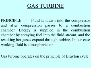
Function • The exhaust duct’s function is to convert post-turbine gas energy into kinetic energy. • This transformation is an expansion; • it is obtained by the shape (convergent in general) of the exhaust duct. • It involves an acceleration of gases. • This acceleration generates a thrust force. • It can be the main thrust of the engine (single flow engines) • or a secondary thrust known as "residual thrust" (double flow engine). CONSTRUCTIONAL FEATURES AND PRINCIPLES OF OPERATION 1 October, 2014
Function CONSTRUCTIONAL FEATURES AND PRINCIPLES OF OPERATION 1 October, 2014
Construction • Joining line. • It comprises an external casing. Inside, a cone (taper) isfixed by struts. • Itsroleis to channel the hot gasesleaving the turbine and to transformtheirannular flow intocircular flow. • The taper. • Itsroleis to streamline the rear face of the turbine. • It can support the rearbearing of the turbine. • Struts. • The number of strutsis variable, depending on the type of engine. • Theyconvey the gas flow in an axial direction. • Struts are hollow and can be thus used, due to fresh air circulating inside, to cool the rear face of the turbine or to pressurize the turbine bearing. • . CONSTRUCTIONAL FEATURES AND PRINCIPLES OF OPERATION 1 October, 2014
Joining line CONSTRUCTIONAL FEATURES AND PRINCIPLES OF OPERATION 1 October, 2014
Taper CONSTRUCTIONAL FEATURES AND PRINCIPLES OF OPERATION 1 October, 2014
Construction • Struts. • The number of struts is variable, depending on the type of engine. They convey the gas flow in an axial direction. • Struts are hollow and canbethusused, due to fresh air circulatinginside, to cool the rear face of the turbine or to pressurize the turbine bearing. • Tail pipe. • It is a cylindrical conduit intended to ensure the connectionbetween the joining line and exhaustnozzle. • Note that it is optional, depending on how the engine is installed in the airframe or in the nacelle. CONSTRUCTIONAL FEATURES AND PRINCIPLES OF OPERATION 1 October, 2014
Construction • Nozzle. • The nozzleenables expansion of gasesleaving the turbine to obtain maximum kineticenergy. • For a givensubsonic speed of gases, the expansion nozzleis convergent in shape. • For a givensupersonic speed of gases, the nozzleis convergent-divergent in shape. CONSTRUCTIONAL FEATURES AND PRINCIPLES OF OPERATION 1 October, 2014
Dual flow turbojet CONSTRUCTIONAL FEATURES AND PRINCIPLES OF OPERATION 1 October, 2014
Fixed area convergent nozzle : Mixed flow bi-pass turbojet CONSTRUCTIONAL FEATURES AND PRINCIPLES OF OPERATION 1 October, 2014
Variable outlet section convergent nozzle : Eyelids CONSTRUCTIONAL FEATURES AND PRINCIPLES OF OPERATION 1 October, 2014
Variable outlet section convergent nozzle : Device with multiple flaps CONSTRUCTIONAL FEATURES AND PRINCIPLES OF OPERATION 1 October, 2014
Primary nozzle, convergent, multi-tab nozzle CONSTRUCTIONAL FEATURES AND PRINCIPLES OF OPERATION 1 October, 2014
Secondary nozzle, eyelids nozzle CONSTRUCTIONAL FEATURES AND PRINCIPLES OF OPERATION 1 October, 2014
Materials • Tail pipe. CONSTRUCTIONAL FEATURES AND PRINCIPLES OF OPERATION 1 October, 2014
Materials • Exhaust Pipe. CONSTRUCTIONAL FEATURES AND PRINCIPLES OF OPERATION 1 October, 2014
Introduction • An exhaust duct is composed mainly: • of a joining line, including an outer jacket and a cone, the function of which is to assure the continuity of gas flow leaving the turbine, • of a tail pipe, ensuring the connection between the joining line and the nozzle. • The tail pipe is optional. • Its installation depends on how the engine is placed in the frame. • of a nozzle of fixed or variable exhaust area, intended to expand and accelerate gases. • Nozzle architecture can vary sharply, and is classified in two groups: • fixed convergent area ducts, found on most commercial aircraft engines, • variable area ducts (convergent or convergent-divergent), found on engines equipped with exhaust reheaters (Concorde or fighter aircraft). CONVERGENT, DIVERGENT AND VARIABLE AREA NOZZLES 1 October, 2014
Exhaust duct CONVERGENT, DIVERGENT AND VARIABLE AREA NOZZLES 1 October, 2014
Nozzle types CONVERGENT, DIVERGENT AND VARIABLE AREA NOZZLES 1 October, 2014
Fixed convergent area nozzle • Single flow turbojet. • On this type of turbojet the exhaust duct is single. It is composed mainly: • of an exhaust cone, including two parts: a casing and an internal cone. • The casing is directly attached to the turbine case. Its shape is convergent. • The internal cone’s function is to adapt the annular section of the flow in the turbine outlet in circular section. • The internal cone is linked to the casing by struts which rectify the flow. • of a duct. On some engines, the duct precedes a tail pipe. • The duct is a convergent channel in which the expansion of hot gases produces their acceleration. CONVERGENT, DIVERGENT AND VARIABLE AREA NOZZLES 1 October, 2014
Fixed convergent area nozzle • Dual flow turbojet. • Double flow turbojets have two ducts. Both flows may be separate: • The exhaust duct containing hot flow enables the expansion and the acceleration of the gas stream in the same way as in single flow turbojets. • This acceleration, however, represents only one small part of the turbofan’s thrust (about 20% on takeoff), and is called residual thrust. • The exhaust duct containing cold flow makes it possible to accelerate the gas stream, which is the main source of a turbofan’s thrust. It is of convergent shape and consists of two partitions. • The internal partition is the casing surrounding hot parts of the gas generator. • The external partition constitutes the rear part of the engine nacelle. It usually features a thrust reverser. CONVERGENT, DIVERGENT AND VARIABLE AREA NOZZLES 1 October, 2014
Fixed convergent area nozzle CONVERGENT, DIVERGENT AND VARIABLE AREA NOZZLES 1 October, 2014
Fixed convergent area nozzle • Variable ejector nozzle. • Engines equipped with variable area nozzles adjust more easily to their flight envelopes (as broad as possible for fighters). • Moreover, engines using re-heaters must be equipped with such nozzles in order to compensate for the increase in mass flow rate. • Variable ejector nozzles are classified in two groups: those with a convergent section and those with a convergent – divergent section • Convergent shapes limit gas exhaust velocities to Mach 1 (in nozzle throat).. • To continue accelerating gases (assuming they still have energy) and reach supersonic exhaust velocities, convergent nozzles must be prolonged with a divergent duct. CONVERGENT, DIVERGENT AND VARIABLE AREA NOZZLES 1 October, 2014
Variable ejector nozzle CONVERGENT, DIVERGENT AND VARIABLE AREA NOZZLES 1 October, 2014
Study of convergent jet nozzles • Fixed exhaust convergent area nozzle. • Space upstream meets the conditions of pressure, temperature, and velocity in the turbine outlet. • The downstreamspacemeets conditions of pressure and temperaturecharacteristic of the atmosphere. • Pt5 = pressure turbine outlet and nozzle inlet • Tt5 = temperature turbine outlet and nozzle inlet • P 0 = atmospheric pressure • T 0 = atmospherictemperature • When pressure Pt5 is higher than P0, a flow originates in the upstream space and moves towards the downstream space. • The larger the differencebetween pressures, the greater the flow • As the nozzleis convergent, gases are accelerated by expansion. CONVERGENT, DIVERGENT AND VARIABLE AREA NOZZLES 1 October, 2014
Study of convergent jet nozzles • Fixed exhaust convergent area nozzle. • If upstream pressure Pt5 continues to increase, gasesreach a maximum speed in the nozzlethroat. • This speed is equal to sonic speed (M=1). • As speed is maximum, sois the gas mass flow rate and thrust. • The relationshipbetween total pressure and static pressure in the throat, known as critical ratio Rc, takes the value : Rc 1,9. • In practice, the real ratio RrisdifferentfromRc. CONVERGENT, DIVERGENT AND VARIABLE AREA NOZZLES 1 October, 2014
Study of convergent jet nozzles • Fixed exhaust convergent area nozzle. CONVERGENT, DIVERGENT AND VARIABLE AREA NOZZLES 1 October, 2014
Study of convergent jet nozzles • Fixed exhaust convergent area nozzle. CONVERGENT, DIVERGENT AND VARIABLE AREA NOZZLES 1 October, 2014
Study of convergent jet nozzles • Fixed exhaust convergent area nozzle. CONVERGENT, DIVERGENT AND VARIABLE AREA NOZZLES 1 October, 2014
Study of convergent jet nozzles • Fixed exhaust convergent area nozzle. • Conclusion: • Every constant section nozzleisadapted to a given altitude and to a preciseturbojetengine rating. • Complete expansion isthuscarried out onlyunderwelldefined conditions. • The ideal compromise isthussoughtwhendesigning an exhaustduct for an engineintended to propel an aircraftatsubsonic speeds. CONVERGENT, DIVERGENT AND VARIABLE AREA NOZZLES 1 October, 2014
Study of convergent jet nozzles • Variable exhaust convergent area nozzle. • For the nozzle to adaptcontinuously to everyengine rating, manufacturers have developedvariousprocesses: • the bucket (or half-shell) system. • the multi-flap system. • Theyallow the adaptation to variousengine ratings. • Theyenable, indirectly, the control of turbine temperature CONVERGENT, DIVERGENT AND VARIABLE AREA NOZZLES 1 October, 2014
Variable exhaust convergent area nozzle: The bucket system CONVERGENT, DIVERGENT AND VARIABLE AREA NOZZLES 1 October, 2014
Variable exhaust convergent area nozzle: The multi-flap system CONVERGENT, DIVERGENT AND VARIABLE AREA NOZZLES 1 October, 2014
Study of convergent - divergent exhaust nozzle • The Mach numberbehind the turbine islowerthan 1 (M < 1). • The ductbehind the turbine always has a convergent shape. • Principle of operation • By connecting a divergent channel to the convergent nozzlafter the throat, the flow canbeaccelerated (Hugoniot’sTheorem) • If the generating pressure Pt5 is sufficient, gases circulate past the nozzle’s throat at Mach 1, and continue expanding in the divergent duct, with an increasing exhaust velocity: M > 1 CONVERGENT, DIVERGENT AND VARIABLE AREA NOZZLES 1 October, 2014
Study of convergent - divergent exhaust nozzle • The convergent-divergent ductenablessupersonicexhaustvelocities (past the throat). • Becauseengine ratings are variable, the divergent duct must alsobe variable. • The primaryductis convergent and has a variable section • The secondaryductmay have a variable section, depending on flight conditions (convergent or divergent). CONVERGENT, DIVERGENT AND VARIABLE AREA NOZZLES 1 October, 2014
Origin of the noise • The streamwise vortices generated in a jet flow, in addition to the azimuthal (or ring type) vortices, have been found to mix fluid streams even more efficiently) • Both the azimuthal and streamwisevorticities are of equal importance to jet mixing process and they are not independent of each other. • The distortion of azimuthal vortex structure may lead to streamwise vortices under certain conditions. • The streamwise vortices in jet mixing flows can be generated by many methods. ENGINE NOISE REDUCTION 1 October, 2014
Exhaust noise ENGINE NOISE REDUCTION 1 October, 2014
Solutions • Flow mixture. • Design enabling flow mixture before their backward ejection. • Significant reduction in exhaust gas noise, and in some cases, an improvement in nacelle aerodynamics. ENGINE NOISE REDUCTION 1 October, 2014
Solutions • Lobed nozzles. • A lobed nozzle used to generate large-scale streamwise vortices in a jet flow has been considered to be a promising method for jet mixing enhancement. ENGINE NOISE REDUCTION 1 October, 2014
Turbofan Lobed Mixer Nozzle ENGINE NOISE REDUCTION 1 October, 2014
Turbofan Lobed Mixer Nozzle ENGINE NOISE REDUCTION 1 October, 2014
Function • Reverse the whole or part of the propelling flow in order to create an aerodynamic braking force. • This makes it possible to assist the braking of the aircraft. • They improve deceleration on slippery runway. • They reduce brake wear. THRUST REVERSERS 1 October, 2014
Location • Generally, thrust reversers are located in the rear part of a single flow turbojet and in an intermediate position in a modern dual flow turbojet. THRUST REVERSERS Single flow turbojet 1 October, 2014 Dual flow turbojet
Study of the gas stream • When analysing the formula, we realize that in order to obtain an effective opposite thrust, are required: • a high aircraft speed (i.e. as soon as possible after landing), • a re-orientation of the ejected flow as forward as possible (manufacturers limit the angle to 45° forward to avoid engine stall and runway remains ingestion). THRUST REVERSERS 1 October, 2014
Principle • Thrust reversers obey the same principle: to try and redirect the propelling flow ahead for it to hit atmospheric air head-on. • So as to avoid interferences between the air sucked by the engine and the reversed flow, the ejection angle of reversed flow is generally limited to 45°. • The unfolding of thrust reversers occurs when engine idles. • Engine rating increases only when the spreading out sequence is completed. • The resulting reversed thrust is about 40% of takeoff thrust (full power). THRUST REVERSERS 1 October, 2014
Various types • Eyelid (shell) type thrust reversers. THRUST REVERSERS 1 October, 2014