Download
1 / 22

E N D
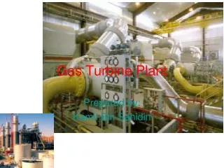
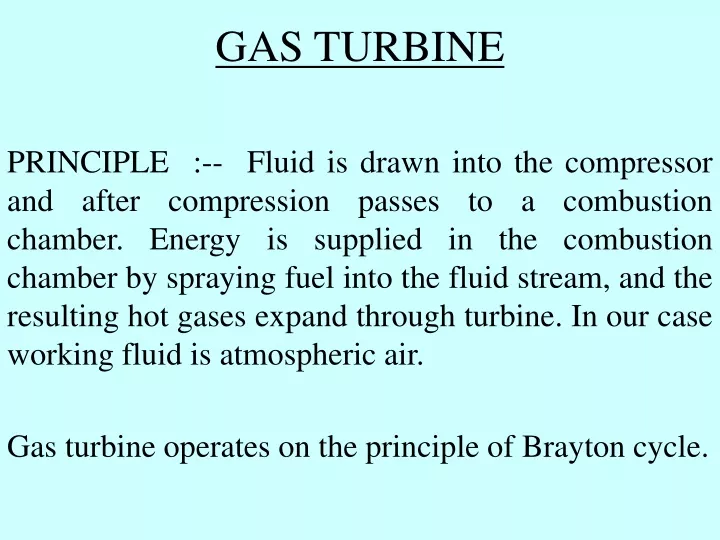
GAS TURBINE PRINCIPLE :-- Fluid is drawn into the compressor and after compression passes to a combustion chamber. Energy is supplied in the combustion chamber by spraying fuel into the fluid stream, and the resulting hot gases expand through turbine. In our case working fluid is atmospheric air. Gas turbine operates on the principle of Brayton cycle.
COMBUSTION 3 BRAYTON CYCLE CHAMBER 2 TURBINE TEMP COMPRESSOR 4 1 COOLING ENTROPY COMBUSTION CHAMBER 3 2 PRESSURE TURBINE COMPRESSOR 1 4 COOLING VOLUME
FUEL EXHAUST CC COMPRESSOR G TURBINE D AIR IN D-DIESEL ENGINE CC-COMBUSTION CHEMBER G-GENERATOR GAS TURBINE
BLOCK DIAGRAM OF GAS TURBINE ATOM. AIR COMP. FUEL AIR FILTER FUEL PUMP COMBUSTION CHAMBER JAW CLUTCH GENERATOR EXITOR DIESEL ENGINE ACC. GEAR MAIN COMP. TURBINE TORQUE CONVERTOR RATCHET DIVERTOR DAMPER MOP MHOP BOOSTER COMPRESSOR BYPASS STACK HRSG
FUNCTIONS OF VARIOUS MAJOR COMPONENTS DIESEL ENGINE: --- It is required to supply a high torque at the time of starting to drive the turbine upto the firing speed and then fire turbine to reach self sustaining speed. It also drives the start up compressor till the main compressor comes into the service. TORQUE CONVERTOR:--- It is used to provide the required torque and speed for the cranking of the turbine. RATCHET:---- The ratcheting system is provided for rotating the shaft either before start up or after the shutdown of the machine. JAW CLUTCH:--- The function of jaw clutch is to engage/disengage diesel engine to gas turbine.
ACCESSORY GEAR BOX:---- Accessory gear box performs the following multiple functions. 1) To drive the various accessories at their designed speed and required torque. 2) To connect and disconnect the tubine from the starting device. 3) To trip the turbine mechanically through over speed bolt mechanism. VARIOUS COMPONENT DRIVEN BY ACCESSORY GEAR BOX ARE. A) Main Hydraulic Oil Pump (MHOP). B) Main Lube Oil Pump (MOP). C) Main Atomising Air Compressor. D) Fuel Oil Pump.
AIR INLET SYSTEM:---- It is required to provide clean air to the compressor from the atmosphere. The atmospheric air passes through a set of filter element and then to the inlet plenum of the main air compressor. MAIN AIR COMPRESSOR:--- Compressor is axial flow type with 17 stages. The compressor suction recieves clean air from the air inlet system. The compressed air is used in GT for the various purposes as described below. A) Combustion of fuel in combustion chamber. B) Cooling of various turbine parts. C) Sealing of oil in bearings. D) Purging of air filters. INLET GUIDE VANES(IGV):---It is located at the after end of inlet casing. The position of these vanes controls the quantity of compressed air flow. Vanes are actuated by a hydraulic cylinder connected to the control ring that turn the individual pinion gears mounted at the end of each vane.
COMBUSTION SECTION:--- The combustion system is reverse flow type. The high pressure air from the compressor reverses its path in the transition pieces and then move to the annular spaces that surround each of ten combustion chambers. EACH COMBUSTION CHAMBER HAS THE FOLLOWING MAIN PARTS:---- a) Nozzle Flow Sleeve b) Liner c) Transition Piece d) Cross Fire Tube e) Spark Plug (2 nos.) f) Flame Detectors(2nos.) FUNCTIONSOF VARIOUS PARTS A) TRANSITION PIECES:--- It directs the hot gases from the liner to turbine nozzle. B) NOZZLE:--- It disperses and mixes the fuel with proper amount of combustion air. C) CROSS FIRE TUBE:--- A passage to propagate the flame from one combustion chamber to another after the initiation of fire by spark plug. D) COOLING OF LINER WALL:--- A film of main compressor discharges air shields the liner wall from the hot combustion gases.
E) COMBUSTION CHAMBER:--- In the combustion chamber, hot combustion gases from the reaction zone passes to the dilution zone where additional amount of air is mixed to bring the temp. of hot gases to desired level. F) SPARK PLUG:--- Combustion is initiated by the spark plugs provided in two combustion chambers when the firing command is given by the Mark - V. The spark plug operates at the voltage of 11 KV & this high voltage is supplied by ignition transformer. G) ULTRA VIOLET FLAME DETECTOR:--- During the starting sequence, it is essential that indication of presence or absence of flame in the combustion chambers be transmitted to the Mark-V. The two nos. flame detectors are provided in combustion chamber no. 7 & 8 to meet the purpose. H) FUEL NOZZLES:--- Each combustion chamber has one nozzle & each nozzle has four inlets for Natural Gas, liquid fuel, Purge air & atomising air. The liquid is atomised by means of atomising air. The swirl tip in the nozzle imparts a swirl in the combustion air for complete combustion and resulting in the smoke free operation of the unit.
TURBINE:--- The turbine has two stages. Turbine section is the area in which heat heat energy in the form of pressurised hot gases produced by the compressor and combustion sections is converted into the mechanical energy. The main parts and features of turbine are described below. A) COOLING OF BUCKETS:--- As the first stage bucket are the first to encounter the extremely hot gases, hence longitudinal holes are provided in these buckets for cooling as air is passes through holes. B) TURBINE ROTOR COOLING:--- Rotor cooling is done by means of a positive flow of cool air radially outward through a space between the wheel and the buckets, then through the stator and finally in to the main gas stream area which is called wheel space. C) FIRST STAGE WHEEL SPACE COOLING:--- The forward wheel space cooling is done by compressor discharge air which is leaking through the labyrinth. This air discharges in to the main gas stream. The aft wheel space is cooled by 2nd stage nozzle cooling air.
D) SECOND STAGE WITH SPACE COOLING:--- Forward wheel space is cooled by leakage from Ist stage aft wheel space through the inter stage labyrinth. Aft wheel space is cooled by air from the internal extraction system. This air enters the wheel space through slots in the forward face of the spacer.
SPECIFICATION OF GAS TURBINE AIR COMPRESS0R 1. NO OF STAGES : 17 2. TYPE : AXIAL FLOW 3. CASING SPLIT : HORIZONTAL 4. COMPRESSION RATIO : 1:10.3 5. RATED SPEED : 5100 RPM 6. EXTRACTION : 4th, 10th & 17th STAGE FOR COOLING, SEALING & AIR FILTER, PULSE CLEANIG. TURBINE 1. NO OF STAGES : 2 2. TYPE : IMPULSE 3. CASING SPLIT : HORIZONTAL 4. MINIMUM CONTINUOUS SPEED : 4896 RPM 5. IGNITION SPEED : 940 RPM 6. SELF SUSTAING SPEED : 2640 RPM 7. MECHANICAL TRIP SPEED : 5737 ± 50 8. ELECTRICAL TRIP SPEED : 5610 +30
COMBUSTION SYSTEM 1. TYPE : REVERSE FLOW 2. NO OF COMBUSTER : 10 3. NO OF FUEL NOZZLE/ COMBUSTERS : 1 4. TYPE OF IGNITORS : AUTOMATIC RETRACTING TYPE 5. NO OF IGNITORS : 2 6. NO OF FLAME DETECTORS : 2 7. TYPE OF FLAME DETECTORS : ULTRA VIOLATE 8. FIRING TEMP. AT BASE LOAD : 963°C AT TRAILING EDGE OF 1st STAGE NOZZLE. 9. FIRING TEMP. AT PEAK LOAD : 996°C.
ISO OUTPUT WITH NG : 26.3 MW IS0 OUTPUT WITH DISTILLATE : 25.8 MW HSD & NAPTHA : FUEL FOR GT & HRGS. HEAT RATE WITH NG : 3021.5 KCAL/KWH HEAT RATE WITH DISTILLATE : 3041.5 KCAL/KWH
TEMPERATURE USED HEAT ENERGY ENTROPY CHART REJECTED HEAT ENERGY ENTROPY
TEMPERATURE USED HEAT ENERGY EFFECT OF INCREASED BACK PRESSURE REJECTED HEAT ENERGY ENTROPY
TEMPERATURE USED HEAT ENERGY EFFECT OF INCREASED STEAM TEMPERATURE & PRESSURE REJECTED HEAT ENERGY ENTROPY
TEMPERATURE ADDITIONAL HEAT INPUT IN THE REHEATER USED EFFECT OF REHEAT ON CYCLE EFFICIENCY HEAT ENERGY REJECTED HEAT ENERGY ENTROPY
3 TEMPERATURE 4 USED HEAT ENERGY 2 REJECTED HEAT ENERGY 1 ENTROPY GAS TURBINE CYCLE
3 TEMPERATURE 4 USED HEAT ENERGY 2 1 REJECTED HEAT ENERGY ENTROPY GAS TURBINE & HRSG COMBINE CYCLE