Download
1 / 33
330 likes | 359 Views
PIXEL. H. Wieman HFT CDO vetting review LBNL 17-Dec-2007. topics. Pixel specifications and parameters Pixel silicon Pixel Readout STAR telescope tests Mechanical organization. Pixel geometry. End view. 8 cm radius. 20 cm. 2.5 cm radius. Inner layer Outer layer. coverage +-1.

E N D
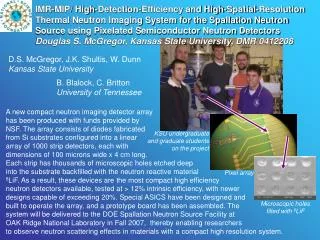
PIXEL H. Wieman HFT CDO vetting review LBNL 17-Dec-2007
topics • Pixel specifications and parameters • Pixel silicon • Pixel Readout • STAR telescope tests • Mechanical organization
Pixel geometry End view 8 cm radius 20 cm 2.5 cm radius Inner layer Outer layer coverage +-1 One of two half cylinders total 40 ladders
Silicon program pixel chips (MAPS) produced by IReS/LEPSI IPHC (Strasburg) M. Winter C. Hu C. Colledani W. Dulinski A. Himmi A. Shabetai M. Szelezniak I. Valin
MAPS • Properties: • Signal created in low-doped epitaxial layer (typically ~10-15 μm) • Sensor and signal processing integrated in the same silicon wafer • Standard commercial CMOS technology
IPHC Functional Sensor Development All sensor families: • 30 x 30 µm pixels • CMOS technology • Full Reticule = 640 x 640 pixel array Mimostar 2 => full functionality 1/25 reticule, 1.7 µs integration time (1 frame@50 MHz clk), analog output. (in hand and tested) Phase-1 and Ultimate sensors => digital output (in development) Data Processing in RDO and on chip by generation of sensor. The RDO system design evolves with the sensor generation. Leo Greiner
MIMOSTAR 2/3 technology Grzegorz Deptuch
Preliminary tests in Saclay of chips with 20 µm and 14 µm thick epitaxy layer • Fe55 tests • Noise and Fixed pattern noise measured • In beam MIP detection efficiency measured with silicon strip telescope IHCP Marc Winter et al
Silicon summary, development of STAR pixels • Finished MIMOSTAR 2 with readout development • Working on MIMOSTAR 3 studies • Fab Phase 1 based on MIMOSA16/22 technology (digital output, no zero suppression) • Fab Ulitimate based on MIMOSA16/22 and SUZE technology (digital with zero suppression) • Issues • MIMOSTAR 3 yield • Radiation hardness (bulk damage) • Reduce temperature • Investigate silicon improvements
Readout system LBNL Leo Greiner Xiangming Sun Michal Szelezniak Thorsten Stezelberger Chinh Vu Howard Matis
System Design – System Blocks • This is a highly parallel system – a schematic representation is shown below.
Sensors, Ladders, Carriers (interaction point) LU Protected Regulators, Mass cable termination RDO Boards DAQ PCs System Design – Physical Layout 1 m – Low mass twisted pair 30 m Power Supplies Platform 3 m - twisted pair 100 m - Fiber optic cables Magnet Pole Face (Low Rad Area ?) DAQ Room Leo Greiner
Detailed System Structure – Sensors and Cables Early prototype cable with 40 differential pair output, clock and control routed under sensor area. Fine twisted pair cables 125 micron diameter wire Soldered directly to cable Low stiffness / mass • 4 LVDS outputs / sensor • Cable • 4 layer - 150 micron thickness • Aluminum Conductor • Radiation Length ~ 0.1 % • 40 LVDS pair signal traces • Clock, JTAG, sync, marker
RDO Board(s) Two board System – Virtex-5 Development board mated to a new HFT motherboard Xilinx Virtex-5 Development Board New motherboard • Digital I/O LVDS Drivers • 4 X >80 MHz ADCs • PMC connectors for SIU • Cypress USB chipset • SODIMM Memory slot • Serial interface • Trigger / Control input Note – This board is designed for development and testing. Not all features will be loaded for production. • FF1760 Package • 800 – 1200 I/O pins • 4.6 – 10.4 Mb block RAM • 550 MHz internal clock Leo Greiner
Detailed System Structure – RDO Functional Data Path – Phase 1
Detailed System Structure – RDO Functional Data Path – Ultimate
Data Rates - Parameters Radius • Rates for L = 3 x 1027 for Phase-1, L = 8 x 1027 for Ultimate. • 2.5 hits / cluster. • 1 kHz average event rate. • 10 inner ladders, 30 outer ladders. • Factor of 1.6 for event format overhead (can be lowered). • No run length encoding. R = 8.0 R = 2.5 200 us Hits / Sensor at L = 8 x 1027. Integration Time 640 us Leo Greiner
Data Rates • Ultimate => 49.7 MB / s raw addresses. => 79.5 MB / s data rate. • Phase–1 => 59.6 MB / s raw addresses => 95.4 MB / s data rate. The dead-time is primarily limited by the number of externally allocated readout buffers!
Stack of 3 MIMOSTAR2 pixel chips, Chip dimension: 4 mm X 4mm, 128 X 128 pixels Prototype test in STAR with 3 Sensor Telescope Our goal was to test functionality of a prototype MIMOSTAR2 detector in the environment at STAR in the 2006-2007 run at STAR. We obtained information on: • Charged particle environment near the interaction region in STAR. • Performance of our cluster finding algorithm. • Performance of the MIMOSTAR2 sensors. • Functionality of our tested interfaces to the other STAR subsystems. • Performance of our hardware / firmware as a system. • The noise environment in the area in which we expect to put the final PIXEL detector.
Telescope Infrastructure at STAR Magnet Pole Tip Electronics Box Beam Pipe Insertion tube
On the fly cluster finding first used with MIMOSTAR analog chips
Distribution of track angles in Mimostar2 telescope Xiangming Sun MichalSzelezniak
Summary of 2007 Au + Au test in STAR • Integrated background small compared to real interaction signals • No noise pickup • Hit rate as expected • Readout system worked well in the STAR trigger DAQ environment • Cluster finding system worked well
Mechanical Program • Eric Anderssen, LBNL engineer working on ATLAS pixels is phasing into our pixel program – full time in April 2008 (carbon composite expert) • Contracted ARES company for analysis on cooling, precision mount design and refinement of ladder stability. • Phone meetings weekly • First stage report due in January
Summary • Silicon design and development carried out by IHCP • additional testing at LBNL • Readout system with STAR integration, well advanced, LBNL • Mechanical work • Project engineer: Eric Anderssen LBNL • Consulting work: ARES corporation, Los Alamos branch
yearly dose numbers • Au + Au • RHIC II luminosity: 7X1027 1/(cm2 sec) • Weeks per year operation: 25 • Fraction of up time: 60% • radius: 2.5 cm • pion dose: 73 kRad • UPC electron dose: 82 kRad • Total dose: 155 kRad • TLD measured projection: 300 kRad • radius: 8 cm • pion dose: 7 kRad • UPC electron dose: 2 kRad • Total dose: 9 kRad • TLD measured projection: 29 kRad