Download
1 / 32
350 likes | 642 Views
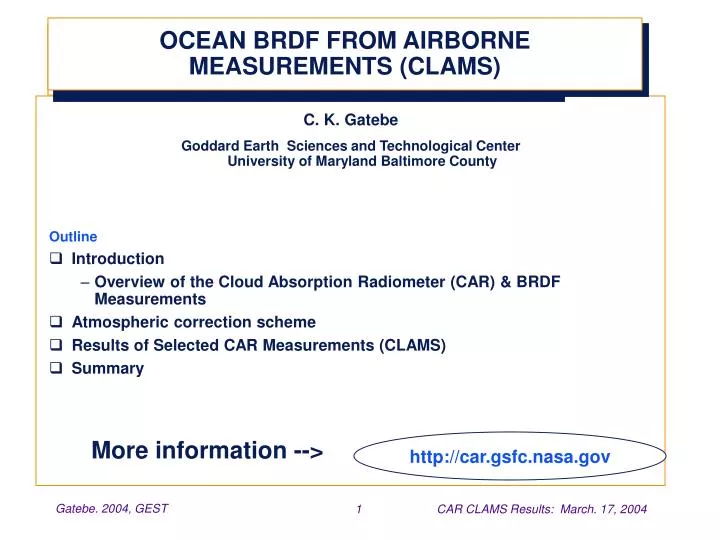
OCEAN BRDF FROM AIRBORNE MEASUREMENTS (CLAMS). C. K. Gatebe Goddard Earth Sciences and Technological Center University of Maryland Baltimore County Outline Introduction Overview of the Cloud Absorption Radiometer (CAR) & BRDF Measurements Atmospheric correction scheme

E N D
OCEAN BRDF FROM AIRBORNE MEASUREMENTS (CLAMS) C. K. Gatebe Goddard Earth Sciences and Technological Center University of Maryland Baltimore County Outline • Introduction • Overview of the Cloud Absorption Radiometer (CAR) & BRDF Measurements • Atmospheric correction scheme • Results of Selected CAR Measurements (CLAMS) • Summary More information --> http://car.gsfc.nasa.gov
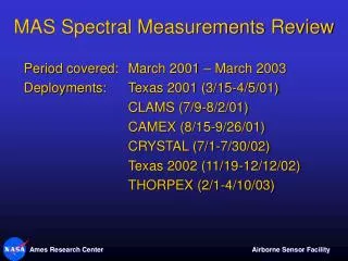
Historical Overview C-131A: 1987-1997 KOFSE: 1991 LEADEX: 1992 SCAR-A: 1993 ARMCAS: 1995 SCAR-B: 1995 TARFOX: 1996 CV-580: 1998-2002 FIRE-ACE: 1998 SAFARI-2000 2004 CLAMS:2001 1982 START Developed 1982-1983 Douglas B-23: Jan-May 1984 ?
Personnel Michael King
CAR: Spectral bands (0.340-2.301 µm)
CAR Timing Wheel START Zenith Auto Zero samples 48° Science Data Dark current Data 64° 190° 42° Eng. Data Nadir
BRDF Measurements 200 m
Mathematical model Lower boundary condition for RT for ocean-atmosphere system: + I(µ, )= Azimuthally independent Cox-Munk model (N&T-1988): Nb. Total BRDF of ocean, R=Rcm+Rw
CAR Atmos. Corr. Model Rewrite the RT equation at the flight level z as: Atmospheric correction is done using:
Atmospheric Correction Steps Step 1: Initialize U = 1 m/s; Aw =0; R=Rcox-munk Step 2: Compute diffuse radiance, Isky and path radiance, Ipath Step 3: Compute the full BRDF for all view angles of the CAR:
Atmospheric Correction Steps Step 4: In the glint region, defined as R > max(Rw,0.02), find the -best-fit wind speed for the difference R-Rw. -Update Rcox-munk. Step 5: Update Rw and compute Aw for zenith angles <60° Step 6: Repeat 2-6 until U and Aw stabilize Nb. Processing is done per channel. Dispersion of U a good quality indicator.
Principal Plane: 0-180° Principal Plane: 270-90° Notation Forward direction (+ve) Backward direction (-ve) Nadir: 0° Sunglint
1.000 U=1 m/s SZA=30° SZA=20° U=2 m/s 0.750 0.500 0.250 0.025 0.019 0.013 0.006 0.000 U=3 m/s SZA=44° U=6 m/s SZA=16° U=9 m/s SZA=21° BRDF at 0.472 µm
0.8 0.472 µm 0.7 0.6 0.5 saturation 0.4 0.3 0.2 0.1 0.0 -80 -60 -40 -20 0 20 40 60 80 Reflectance in the Principal Plane 10 July; 20°; 2; 278° 17 July; 16°; 6; 7° 23 July; 30°; 1; 227 26 July; 21°; 9; 350° 30 July; 33°; 11; 136° 31 July; 21°; 8; 197° Reflectance 02 Aug.; 44°; 3; 217° Scan Angle (°)
0.14 0.472 µm 0.12 0.10 0.08 Reflectance 0.06 0.04 0.02 0.00 -80 -60 -40 -20 0 20 40 60 80 Scan Angle (°) Reflectance (Perpendicular Plane) 10 July; 20°; 2; 278° 17 July; 16°; 6; 7° 23 July; 30°; 1; 227 26 July; 21°; 9; 350° 30 July; 33°; 11; 136° 31 July; 21°; 8; 197° 02 Aug.; 44°; 3; 217°
0.045 0.024 U=1 m/s SZA=30° U=2 m/s SZA=20° 0.040 0.020 0.035 0.030 0.016 0.025 0.012 0.020 0.015 0.008 0.010 0.004 0.005 0.000 0.000 -80 -60 -40 -20 0 20 40 60 80 0.024 U=3 m/s SZA=44° Scan Angle (°) 0.020 0.016 0.012 0.008 0.004 0.000 -80 -60 -40 -20 0 20 40 60 80 Scan Angle (°) Water-leaving Reflectance 0.472 µm 0°/90° Planes 0.682 µm 0°/90° Planes 0.870 µm 0°/90° Planes
Coastal waters Deep Ocean 0.020 0.035 U=9 m/s SZA=21° U=8 m/s SZA=21° 0.030 0.016 0.025 0.012 0.020 0.015 0.008 0.010 0.004 0.005 0.000 0.000 -80 -60 -40 -20 0 20 40 60 80 -80 -60 -40 -20 0 20 40 60 80 Scan Angle (°) Scan Angle (°) 0.472 µm 0°/90° Planes 0.682 µm 0°/90° Planes 0.870 µm 0°/90° Planes Water-leaving Reflectance
BRDF (water-leaving) at 0.472 µm July 23 July 10 Aug 02 0.020 0.016 0.000 0.006 0.013 0.019 0.025 0.012 0.008 July 10 July 10: 20°; u=2 m/s 0.004 July 23 July 23: 30°; u=1 m/s Aug 02 0.000 Aug. 02: 44°; u=3 m/s -80 -40 0 40 80 Scan Angle (°)
BRDF at 0.682 µm July 10 July 23 Aug 02 0.020 July 10 0.016 July 23 0.000 0.006 0.013 0.019 0.025 0.012 Aug 02 0.008 July 10: 20°; u=2 m/s 0.004 July 23: 30°; u=1 m/s 0.000 Aug. 02: 44°; u=3 m/s -80 -40 0 40 80 Scan Angle (°)
BRDF at 0.870 µm July 10 July 23 Aug 02 0.020 July 10 0.016 July 23 0.000 0.006 0.013 0.019 0.025 0.012 Aug 02 Note: 0.008 July 10: 20°; u=2 m/s 0.004 July 23: 30°; u=1 m/s 0.000 Aug. 02: 44°; u=3 m/s -80 -40 0 40 80 Scan Angle (°)
Message for Remote Sensing Water-leaving radiance seems to be only slightly sensitive to nadir angles ( ≤ 60°) regardless of the sun angle - particularly those sun angles in the range observed in this study. Water-leaving radiance is a major contributor of the total radiance at nadir angles where the total radiance is small. These results are consistent with calculations made by e.g. Plass et al. (1975) Applied Optics, Vol. 14, No. 8, 1924-1936
Albedo Solar Zenith Angle (°) Ocean Albedo (Black Sky) A(0.472 µm)=0.046±0.004 A(0.682 µm)=0.029±0.003 A(0.870 µm)=0.026±0.002
Deep Ocean Albedo Solar Zenith Angle (°) Ocean Albedo (White Sky) A(0.472 µm)=0.016±0.005 (0.014±0.002) A(0.682 µm)=0.004±0.002 A(0.870 µm)=0.002±0.001
0.20 0.10 0.00 -0.10 -0.20 Validation of Cox-Munk Model Difference: R(measurements-CoxMunk)/Rmax High Glint Isotropic anisotropic Anisotropic-GC Low Glint Difference: R(measurements-CoxMunk) 0.015 0.00 -0.015
Cox-Munk Validation cont. 0.60 0.60 High Glint: July 31 High Glint: July 23 0.40 0.40 0.20 0.20 R (Meas. - CM)/Rmax 0.00 0.00 0.20 0.20 0.40 0.40 0.60 0.60 40 50 30 10 -10 50 30 20 10 70 Scan Angle (°) Scan Angle (°) 0.012 Low Glint: July 31 0.008 0.004 R(Meas - CM) 0.000 -0.004 -0.008 -0.012 -25 -30 -35 -40 -45 -50 Scan Angle (°)
Summary • Unique BRDF measurements • Full Angular coverage • Fine angular resolution • High SNR even over dark scenes • Auxiliary data • AATS • Buoy data • Chemistry