Download
1 / 5
50 likes | 147 Views
Next Screen, Page Down. Common Problems and Resolutions. Initial Scanner Installation Problems The initial installation of the (TS4120) and the USB drivers is where the majority of problems show up.

E N D
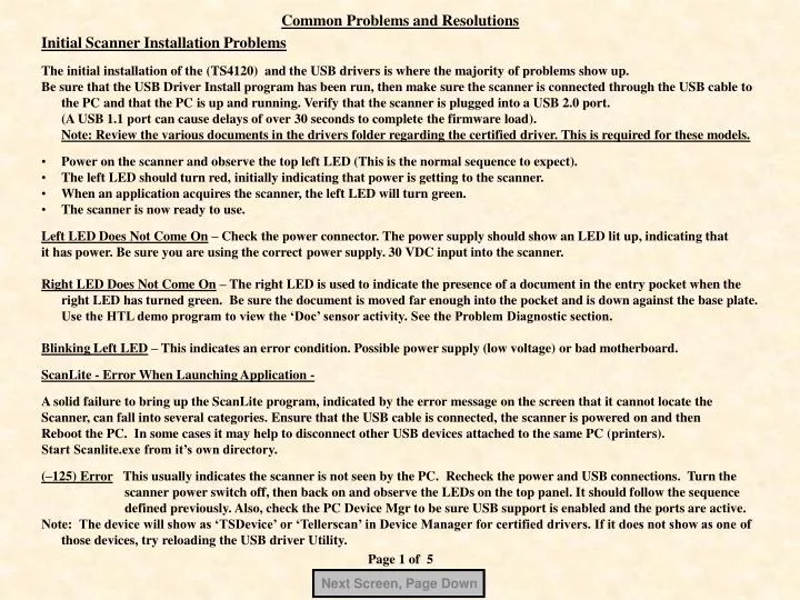
Next Screen, Page Down Common Problems and Resolutions • Initial Scanner Installation Problems • The initial installation of the (TS4120) and the USB drivers is where the majority of problems show up. • Be sure that the USB Driver Install program has been run, then make sure the scanner is connected through the USB cable to the PC and that the PC is up and running. Verify that the scanner is plugged into a USB 2.0 port. • (A USB 1.1 port can cause delays of over 30 seconds to complete the firmware load). • Note: Review the various documents in the drivers folder regarding the certified driver. This is required for these models. • Power on the scanner and observe the top left LED (This is the normal sequence to expect). • The left LED should turn red, initially indicating that power is getting to the scanner. • When an application acquires the scanner, the left LED will turn green. • The scanner is now ready to use. • Left LED Does Not Come On – Check the power connector. The power supply should show an LED lit up, indicating that • it has power. Be sure you are using the correct power supply. 30 VDC input into the scanner. • Right LED Does Not Come On – The right LED is used to indicate the presence of a document in the entry pocket when the right LED has turned green. Be sure the document is moved far enough into the pocket and is down against the base plate. Use the HTL demo program to view the ‘Doc’ sensor activity. See the Problem Diagnostic section. • Blinking Left LED – This indicates an error condition. Possible power supply (low voltage) or bad motherboard. • ScanLite - Error When Launching Application - • A solid failure to bring up the ScanLite program, indicated by the error message on the screen that it cannot locate the • Scanner, can fall into several categories. Ensure that the USB cable is connected, the scanner is powered on and then • Reboot the PC. In some cases it may help to disconnect other USB devices attached to the same PC (printers). • Start Scanlite.exe from it’s own directory. • (–125) Error This usually indicates the scanner is not seen by the PC. Recheck the power and USB connections. Turn the scanner power switch off, then back on and observe the LEDs on the top panel. It should follow the sequence defined previously. Also, check the PC Device Mgr to be sure USB support is enabled and the ports are active. • Note: The device will show as ‘TSDevice’ or ‘Tellerscan’ in Device Manager for certified drivers. If it does not show as one of those devices, try reloading the USB driver Utility. Page 1 of 5
Next Screen, Page Down Common Problems and Resolutions Document Feeding Problems There are 6 common feeding error codes that show up using ScanLite. These same codes should also be displayed by any imaging application using the TS4120 scanners. (-212) No checks in the feeder – This occurs when a scan cycle has be initiated, but no documents are detected in the entry area. While this error can happen simply by manually selecting a scan with no documents present, it could be that the ‘Check Present Sensor’ is not functioning properly. Check that it is not blocked and appears to cycle on and off when a document is placed, then removed from the entry hopper. TIP: The inner sensor might have been bent so that is is no longer lined up with the outside sensor. Push the pusher bar back all the way and observe the alignment. (-216) No feeding. Unable to load document. –This occurs when the first document in the stack did not make it to the Sync sensor in the given amount of time. Typical causes are that the document(s) have a heavily curled or bent front edge or front lower corner. This causes the documents to catch or be slowed up getting through the double feed rollers. If you have not cleaned the unit in a while perform that first. Then review the Double Feed Roller Adjustment for adjusting the setting and retest. (-217) Two or more documents in the check path –This error is probably the most common. It can be caused by scanning very slick, new documents or documents stuck together with static. Check the Double Feed Roller Adjustment and tighten 1/2 turn and retest. See the adjustment for the TS4120. TIP: Sometimes proper document preparation is needed by handling the documents, sorting through them or providing a slight indent so the papers are not so flat. Use of a jogger device can also improve the feeding. This helps to remove excess static and to allow better separation. (-219) Top Cover Not Fully Seated – Reseat the top center cover and launch the application again. If it still fails, check that the magnet is still attached to the underside of the cover near the turnaround roller area. (-220) Document is jammed in track– The-220 error code is a fairly common error and can occur for a variety of reasons. This typically indicates that a document was stopped in the track, slowed in the track or did not fully exit on time. See the next page, ( page 3), for more detailed information for causes of -220 errors. (-553) No Print Head – Check that an ink jet cartridge is installed. If it is, pull out and reseat the cartridge. Try a new cartridge. The ribbon connector cable going to the main board maybe need to be reseated or the main board may be bad. Page 2 of 5
Next Screen, Page Down Common Problems and Resolutions • Document Feeding Problems (Causes for -220 errors) • First, define the jamming symptom- Where does the leading edge of the document stop when the error occurs? • a) It did not make it to the sync sensor - look for a bad or misaligned sync sensor which shows active all of the time. • b) It’s just before or entering the scanheads - There could be interference from the ink jet platform or the MICR read head.Visually look down from the top to observe the clearances. You should see some clearance where the ink jet platform is not catching the leading edge and that the MICR head backup roller is touching the head, but rotates freely. Open the scanhead area to check for debris on the walls or lens and rollers hung up or out of position. Check for wall clearance (see Adjustment section). • c) It’s just before or after the first turn - Check the two path idlers for binds. Rotate the main drive turnaround roller to move the entire belt drive and feel for abnormal effort needed to turn the rollers. This could be caused by a binding bearing, idler or stepper motor. NOTE: Run the TS4120 Config Update program (on this CD) to improve timing. (Prior to early 2009) • TIP: You can turn the last main drive roller by hand and walk a document through the path slowly to determine if it’s catching on something. Use ScanDemo or ScanLite and the Eject function to run documents through the scanner at full and half speeds to test under power. • Check that the application is using TS2DLL.DLL (V4.4.3 or higher). This provides the proper code level to run a TS4120. Important: The TS440Firmware.bin file also needs to be checked. It should be at a compatible level with the TS2dll.dll. • Check with Digital Check if there is a question about code levels. Typically, if the demo code works and the application does not, then a code level mismatch is likely. Since late 2007, TS2dll V4.4.3 and firmware V1.0.3.0 (319,560 bytes) is stable and is what comes with the API files in V8.70. The TS4120 works best on API code V8.7X or newer. • d) Clean Entry & Drive Rollers- Thoroughly clean the entry and main drive rollers using the cleaning cards and a cleaning swab. • e) Jamming Entering Exit pocket – Checks that catch going into the exit pockets, specifically the outer pocket, may be severely folded or not sliding down far enough. Reforming the Mylar strip or reducing the spring tension on the first flap can help the check to slide further into the pocket. • No Motor Start - If the scan cycle is started but the motor does not start, it could be a bad Sync or exit sensor or check that the unit has an ink jet cartridge installed. Most applications expect the cartridge, but they do not always pass on the error. • Check that the center cover is seated and has the small magnet on the underside near the large turnaround roller end. Page 3 of 5
Next Screen, Page Down Common Problems and Resolutions Image Quality Problems - Run a TIF image and a 16 shade gray scale of the same check as a reference point before you start. Heavy Background – Make sure the scanhead lens are clean (see Cleaning section). Use ScanLite to run a BW mode image which gives a bitonal front and rear (uses 200x200 dpi). Then run the same check using Gray to BW mode. The top image should be acceptable and show little or no significant background. If it still looks too dark, run the Scanhead calibration procedure. Check and reseat the connectors going to the CIS modules. If it still fails, replace the camera module and recalibrate. Blotchy or Faded Areas - Check that the inner door is fully seated. Scan a standard, clean background check using Gray Scale mode. This should give you a reference image that shows whether the image has a uniform shading or exhibits voids or streaking across the document. If it does not look fairly uniform, then run the Scanhead calibration procedure (see Maintenance Program section). Camera Lens Page 4 of 5
Next Screen, Page Down Common Problems and Resolutions MICR Errors – Test the MICR with a set of known good checks to use as a reference. Random MICR Errors – Random @ symbols showing up along the top of the Scandemo screen indicates an erratic failure. Check that there are no power supply or other electromagnetic devices within six inches of the scanner. Run through the cleaning procedure (see Supplies & Cleaning section) to properly clean the entry and main drive rollers so that they are not slipping when moving the document. Visually look down where the MICR read head is in the outer path. The spring loaded backup roller should be visibly touching the MICR read head. Make sure that the ink jet platform is not skewed or interfering with the document path. Important - Review the Adjustment & Removals section regarding drive belt tension. Too tight and the belt can ‘cog’ or bind. Too loose and the slack can cause jitter when a character is running across the head. Specific MICR Errors - @ symbols that continually show up in the same position on the MICR line could indicate a drive path problem. Check for binds in the drive belt by turning it through several complete cycles. Review the Adjustment & Removals section regarding double feed adjustment. Also look for binding or broken idler rollers in the path or something catching the leading edge of the document in the scanhead area. The double feed adjustment may be too tight or not vertically aligned properly. Ink Jet Testing – You can use ScanLite to test the inkjet. Select the Endorse box on the ScanLite screen. A pre-defined print string will print on the document. If ScanLite works and the application does not, it is not a scanner hardware issue. The ink jet cartridge may need to be reseated by carefully removing it and re-inserting it. Be sure that the cartridge snaps into place. See TS4120 Service Manual section 3.11. The ink is water based so use a damp cloth to wipe across the nozzles horizontally to clean the print head. MISC: Scanner stops talking to the PC – Symptom -The scanner will appear to disconnect from the PC when sitting idle for a period of time. Resolution – If you are not sure if the V2.6 USB Utility was used, you can turn off the power management feature manually. Turn off the Power Mgmt feature for each USB Root Hub under Windows Device Manager for USB Devices. Open Properties for each Root Hub, then the Power Mgmt tab. Reboot the PC. Note: See the User Manual on this CD for the errors and cleaning information. This could be printed out as a handout to the user. Page 5 of 5