Download
1 / 27
270 likes | 390 Views
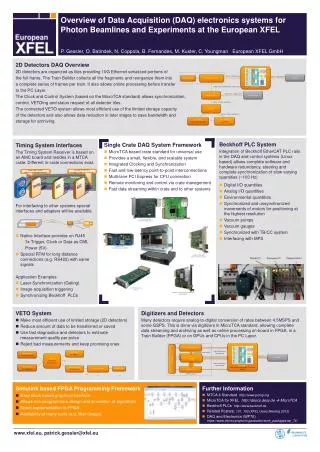
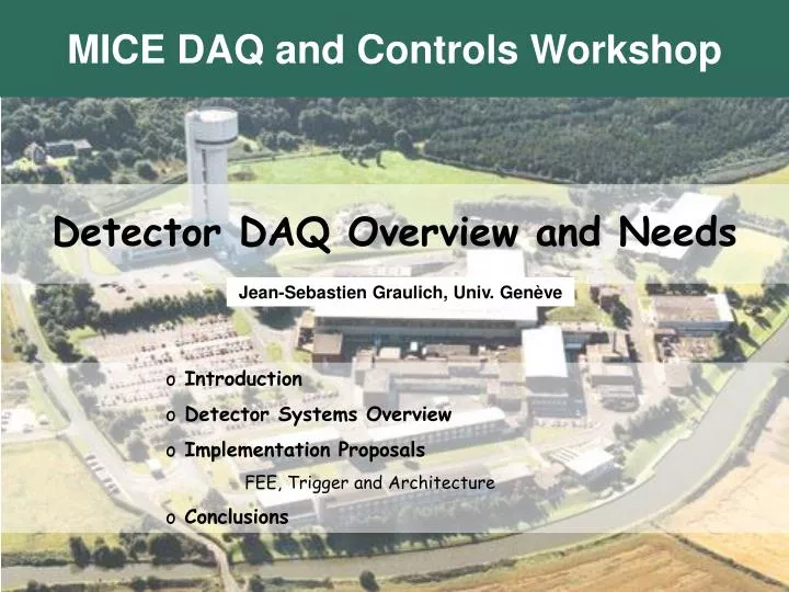
MICE DAQ and Controls Workshop. Detector DAQ Overview and Needs. Jean-Sebastien Graulich, Univ. Genève. Introduction Detector Systems Overview Implementation Proposals FEE, Trigger and Architecture Conclusions. Introduction. Normal Detector DAQ is synchronised with MICE Beam

E N D
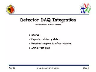
MICE DAQ and Controls Workshop Detector DAQ Overview and Needs Jean-Sebastien Graulich, Univ. Genève • Introduction • Detector Systems Overview • Implementation Proposals FEE, Trigger and Architecture • Conclusions Jean-Sébastien Graulich
Introduction • Normal Detector DAQ is synchronised with MICE Beam • We want RF ON and RF Off Data • (50/50 ?) • We need calibration data • For each run • We want RF Noise data • Dedicated Run Jean-Sébastien Graulich
DDAQ vs CM Detector DAQ Synchronised with the beam Very fast reaction time (~ms) High transfer rate (~50 MB/s) Read and Store, no time for on-line processing Limited User InterfaceRun Control only (Slow) Control and Monitoring Continuous and permanent Very reliable (Safety issue) Deal with a lot of ≠ hardware Read and CheckCalibration, manage alarms at ≠ levels, soft interlocks, take actions, log history, etc. Extended UISet many parameters, manage complicate initialisation procedures, etc. • Why separate Particle Detector DAQ and Control Sensor DAQ ? Jean-Sébastien Graulich
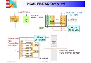
Slow Control Detector DAQ RF Phase Concept Schematic MICE User Interface Run Control UI Monitoring Data Log Data Storage Environment MICE Beam Line MICE Cooling Channel MICE Detectors Jean-Sébastien Graulich
Definitions and assumptions • Definitions • Machine Cycle: • 50 Hz (20 ms) Injection/Extraction cycle of ISIS • MICE Target Cycle -> Spill Cycle • Beam ON / RF ON • Beam ON / RF OFF • MICE RF Cycle • RF duty factor: 10-3 • ~100 ms ramping up/down time • Most efficient cycle: ~1ms long RF pulse every second • Assumptions (from TRD) • The aim is to collect 600 good muons per spill • Instantaneous rate = 0.6 MHz (1.7 ms between 2 muons) • A good muon is a traversing muon (~ 1/6 in phase with RF) • 106 muons per setting is required (1700 spills, 30 min) -> 2 spills/second (~1ms long) Jean-Sébastien Graulich
Readout Cycle • Particle-by-particle readout is not possible: • Readout takes a few 100 ms (depends on the data size) • Readout time ≠ Conversion time • Readout time driven by the slowest VME crate • => Detector Data has to be buffered in the FEE modules • Buffer size ~ 600 muon events • => Readout performed at the end of the spill • Normal DAQ Event triggered by Start of Spill • Normal DAQ Event ≠ Particle Event Jean-Sébastien Graulich
The ADC problem • Even simple gated ADC is a problem • Conversion time > ~3 ms • = 2 x the average time between two muons • Gated ADC => maximum 300 muons/spill • If buffer size high enough (common is 30 evts!) • Alternative: Flash ADCs • The full waveform is digitised for the whole spill • Sampling rate > 200 MHz (1 sample/ 5ns) • 200 106 sample/channel/spill • If 8 bits data -> 200 MB/ch (or nearly 400 GB/ch/run) • => Data size problem • No time to transfer • No space to store => Need zero suppression • Nobody works on that !!! Jean-Sébastien Graulich
Detector System Overview • 5 detector systems • 2 Tracker modules (5 Sci.Fi stations) • 3 TOF stations • CKOV1 Upstream • CKOV2 Downstream • EmCal Jean-Sébastien Graulich
Sci.Fi Tracker • Main requirements: • Efficiency, Spatial Resolution, low sensitivity to RF bg • Number of channels: • 4096 ADC per tracker = 8192 ch • 8192 TDC channels under development (AFE-T) • Front End Electronic: • Analog to Digital: AFE II • VME (digital data buffer): VLSB (512 ch/module) • Word size: • 10 bits for ADC, • Probably ~12 bits for TDC • 13 bits for the channel number • (+ data overhead) • Average Data Size • Without zero suppression (no TDC): 24 kB/μ • With zero suppression and TDC: 0.25 kB/μ Jean-Sébastien Graulich
Sci.Fi Tracker Constraints Important limitations: • Read out has to be synchronised with the beam microstructure • Built in the AFE board, designed for D0 • 100 ns muon burst every 320 ns (Compared to D0: 150 ns burst every 400 ns) • Looks OK • AFE Conversion time: ~6.5 microseconds • 600 muons/spill is NOT possible New assumption: Maximum 150 muons per spill (2h/run) Jean-Sébastien Graulich
Time Walk TOF • Main requirements: • Time resolution ~70 ps, high rate (2.5 MHz in TOF0) • Number of channels: • (48 + 32 + 32) TDC = 112 ch • 112 ToT (Time over threshold) for time walk correction • Front End Electronic: • CAEN 1290 • Word size: • 16 bits/ch • Average Data Size • 0.1 kbyte/muon Jean-Sébastien Graulich
TOF FEE • Proposed FEE module: • Multi-Events, Mutli-Hits • Not tested yet Jean-Sébastien Graulich
Event Integrity • How to retrieve particle event integrity ? • Easy at the DAQ Event Level • What about the Particle Event Level ? Jean-Sébastien Graulich
DAQ and Muon Triggers Normal DAQ Trigger SoS EoS DAQ Gate Good Muons (TOF0xTOF1xTOF2) Muon Trigger to AFE II Muon Trigger to TDC Programmable delay Programmable delay AFE Gate Clock TDC Event Window Progr. Width Jean-Sébastien Graulich
Data Structure Jean-Sébastien Graulich
CKOV1 • Main requirement • Energy resolution: Threshold between pion and muons • Number of channels: • 4 TDC ch • 4 QDC ch • Front End Electronic: • TDC : CAEN 767 ? • QDC : ?? • Word size: • TDC : 20 bits/ch • ADC : probably 10 bits • Average Data Size • ~ 25 bytes/muon (15 kB/spill) Jean-Sébastien Graulich
CKOV FEE • Possible FEE module: • Also Multi-Events, multi-Hits • -> Same Event Integrity check • Not tested yet Jean-Sébastien Graulich
CKOV2 • Main requirement • Low energy threshold • Number of channels: • 12 TDC ch • 12 QDC ch • Front End Electronic: • TDC : CAEN 767 ? • QDC : ?? • Word size: • TDC : 20 bits/ch • ADC : probably 10 bits • Average Data Size • ~ 75 bytes/muon (60 kB/spill) Jean-Sébastien Graulich
Muon Identifier (EmCal) • Main requirement • Energy resolution • Number of channels: • 240 QDC ch • ~60 TDC ch • Front End Electronic: • Not chosen (see ADC Problem) • Word size: • ??? • Average Data Size • I guess ~ 1kB/muon Jean-Sébastien Graulich
Data Volume Summary • All detectors: • 25 kB/μ (1 kB/μ if zero suppression in the tracker) • 7 MB/spill (if 2 x 150 μ/spill) • 25 GB/run (if 106μ/run) • How many runs ? • 2 hours/run • 50% overhead (setting changes) • 80% efficiency • 1 year, 7/7, 24/24 (just to get an idea) • => ~ 2500 runs • Need storage space for ~ 60 TB/year Jean-Sébastien Graulich
Event types • Normal DAQ Event ~ Spill • Calibration Events (Can be Single Gated !) • Pulser events • Full readout, full event building • Pulses generated by the DAQ • Cosmic/source events ? • Partial readout, partial event building • Pedestal events ? • Only ADC readout, full event building • Special muon event with dedicated beam ?? • Special DAQ Events • Start of Spill (SoS) and End of Spill (EoS) can be used to check the synchronisation between subsystems. • No readout, full event building • Each different Event Type requires a dedicated trigger receiver IO channel in each crate ! Jean-Sébastien Graulich
Trigger Receiver • Need at least • 6 inputs • SoS and EoS Events • Normal DAQ Events • Calibration Events: Pedestal, pulser and source/cosmics • 7 outputs • 6 Individual busies • One common busy • More I/O = more flexibility • One module per crate ! • Possible Choice: • CAEN V977 Jean-Sébastien Graulich
“VME” Processors • Needed to collect data locally, at the crate level. • Could be VME processor or External PC • External PC under Linux connected with a VME to PCI optical link is easy, flexible and widespread • Easier if all VME have the same interface • Possible choice: • CAEN V2718 Jean-Sébastien Graulich
DAQ Architecture Jean-Sébastien Graulich
Conclusions • Detector data Readout must be performed at the end of the spill • Data has to be buffered in FEE • Maximum 150 muons/spill (2h/run) • Due to Conversion time in AFE II of Sci.Fi Tracker • Charge Measurement in the Muon Identifier (EmCal) is an issue • A Detector DAQ conceptual scheme already exists • Based on HARP experience • It’s Time to write Specifications ! Jean-Sébastien Graulich