Download
1 / 22
240 likes | 387 Views
BMFB 3263 Materials Characterization. Scanning Probe Microscopy & Relates Techniques Lecture 5. SPM is a technique to examine materials with a solid probe scanning the surfaces; It examines surfaces features whose dimensions range form atomic spacing to a tenth of a millimeter;

E N D
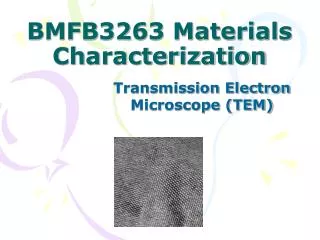
BMFB 3263 Materials Characterization Scanning Probe Microscopy & Relates Techniques Lecture 5
SPM is a technique to examine materials with a solid probe scanning the surfaces; • It examines surfaces features whose dimensions range form atomic spacing to a tenth of a millimeter; • SPM considered the most powerful tool for surface structure examination currently available because it lets ‘see’ atom; • SPM started with the scanning tunneling microscope (STM): • An STM uses tunneling current, a phenomenon of quantum mechanics, to examine material surface; • The tunneling current flows through an atomic-scale gap between a sharp metallic tip and conducting surface atoms;
SPM added a popular member, the scanning force microscope (SFM); commonly called atomic force microscope (AFM): • It uses near-field forces between atoms of the probe tip apex and the surface to generate signals of surface topography; • The AFM more widely used than the STM because it is not restricted to electrically conducting surface;
Instrumentation • The main characteristic of the SPM is a sharp probe tip that scans a sample surface; • The tip must remain in very close proximity to the surface because the SPM uses near-field interactions between the tip and a sample surface for examination; • enable to obtain a true image of surface atoms, it can accurately measure the surface atom profiles in the vertical and lateral directions; • SPM must operate in a vibration-free environment because the probe is only an atomic distance away from the examined surface;
An SPM system consists of several basic components: probe and its motion sensor, scanner, electric controller, computer and vibration isolation; • Please find what is application of this component; I will ask you in test and exam…………..
Scanning Tunneling Microscopy (STM) Based on quantum mechanical “tunneling” effect – when 2 electrodes (2 metals) are brought sufficiently close together to allow overlapping of electronic wave functions associated with each electrode. Apply small bias voltage – tunneling current is formed in direction given by the sign of applied voltage. Use very sharp tip (one atom’s) possible to detect current variation as tip is scanned across surface. Samples must be conductive but medium can be air, liquid or vacuum. Resolution up to nanoscale range.
The reason for extreme magnification capabilities of the STM down to atomic scale is mainly the physical properties of the tunneling current. The tunneling current it has very important characteristic – it exhibits an exponentially decay with an increase of the gap d. Very small changes in tip-sample separation induce large changes in tunneling current!!
Schematic of STM principle - It works by holding a very fine needle or tip approximately a billionth of a meter from the sample's surface. When the tip is this close, electrons can jump the gap between it and the sample. This 'tunnel current' can be amplified and used to measure the size of the gap with tremendous accuracy. An electronic feedback system is used to keep the current (and hence the gap) constant as we move the tip sideways across the surface. Because the current detection is so sensitive the tip actually has to ride up over the atoms of the surface in exactly the same way that a record player's stylus tracks the groove of an LP. By recording the tip's vertical position at points on a grid we can make a 3D map of the surface.
Circular ‘quantum’ corral 48 iron atoms positioned on copper (111) at very low T (4K), corral 14.3 nm. Image shows contour of local density of electron states or quantum state of the corral.
The making of circular corral – positioned 48 iron atoms into circular ring.
Scanning tunneling microscopy (STM)of a (105) facetted Ge hut cluster formed by 5.8 monolayer (ML) of Ge on a Si (100) surface STM can take atomically resolved pictures of the electron clouds surrounding surface atoms. It can tell the difference between electrons with different energies, and map their positions independently of each other. Thus STM is a very powerful tool for investigating surfaces.
Each bright bump in the pattern is one Si atom. The beauty of this microscope is not just that it can see the atoms and their regular arrangement on the surface, but that it can also see defects such as the few positions where atoms are missing. The only other microscope that can resolve atomic detail, the electron microscope, uses diffraction from rows of atoms to form its image and so cannot detect a single missing atom like this. Since the electrical conductivity of semiconductors like Si is largely determined by the defects in the materials rather than the properties of the pure lattice, this sort of image is very useful to people like chip makers who want to know exactly what is going on in their devices. Modern chips are made up of elements as small as forty of these pictures side by side, so even single atom defects can be important.
Atomic Force Microscopy (AFM) Operates by measuring forces between sample and probe tip. Force depends on nature of sample, probe geo., spring constant of probe, distance between probe & sample, and any contamination on surface. An atomically sharp tip is scanned over surface with feedback mechanisms that enable the piezo-electric scanners to maintain the tip at a constant force (to obtain height info) or height (to obtain force info) above the sample surface. Tip is brought close enough to surface to detect repulsive force between atoms in tip and sample.
Atomic Force Microscopy (AFM) Probe tip is mounted on cantilever. Interatomic forces will induce bending and can be detected by laser beam.Tips typically made of Si3N4 or Si . Surface topography of sample is tracked by monitoring deflection of the cantilever. Optical detection system – diode laser is focused onto the back of a reflective cantilever. As tip scans surface, moving up & down with the contour, laser beam is deflected off into a dual element photodiode. Measures difference in light intensities between upper & lower photodetectors & converts to voltage.
AFM uses forces when 2 objects are brought within nano-range of each other : probe in contact with surface – repulsive force, a few nm away – attractive force.
Commercial AFM tip, and images taken by nanotube tip compared to normal tip
Digital video dics surface (10 microns). Applications include materials evaluation (surface roughness on implanted Si wafers, nanomechanical testing, surface profiles), failure analysis (defect analysis of compact disc stampers), quality control (surface profiles of thin film & coating, surface finish of substrates for thin film deposition).
Silica spheres homogeneously covered with Ag nanoparticles AFM showing all atoms within hexagonal graphite unit cells, image size 2x2 nm2
Applications STM – characterization of surface structure on atomic scale. Produce topographic map of the surface. AFM – surface topography, depth profiling, hardness at atomic level. Typically applied to studies of phenomena such as abrasion, adhesion, cleaning, corrosion, etching, friction, lubrication, plating & coating, & polishing. Limit : STM – only for conducting materials. Image interpretation also difficult if more than one type of atom on surface.
AFM compared to others : STM – only to conducting but AFM applied to both. AFM also more versatile. In some cases, STM has better resolution because exponential dependence of tunneling current on distance. SEM – AFM provides extaordinary topographic contrast, direct height measurements & unobscured view of surface features (no coating necessary). TEM – 3D image of AFM obtained without expensive sample preparation & yield far more complete info than 2D profiles from cross-sectioned sample.