Download

1 / 34
400 likes | 717 Views
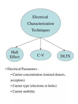
Modern techniques of materials characterization. Basic concept. Source – What kind of „probe“ is used? How does the probe reach the sample? Interaction between probe and sample How does the signal of interest reach the analyzer? Characteristics of the analyzer .

E N D
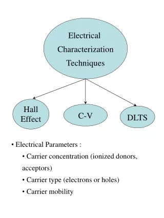
Basic concept • Source – What kind of „probe“ is used? • How does the probe reach the sample? • Interaction between probe and sample • How does the signal of interest reach the analyzer? • Characteristics of the analyzer
What kind of probes are available? • Each and every analysis technique is based on the interaction between a probe and a sample. The following probes are generally available: • Electrons - Hot cathode, field emission • Ions - Plasma, liquid metal tips • Neutrons* - Nuclear reactions (e.g. Spallations-sources) • Photons - Laser X-ray Synchrotron radiation • Heat* - … • A field* - electric, magnetic fields
Analysis Techniques (principle) Signal Probe
Analysis of the structure • Usually one starts with the direct physical imaging of a sample surface • Optical microscope • SEM/Auger (scanning electron microscopy) • TEM (transmission electron microscopy) • STM/AFM (scanning tunneling microscopy / atomic force microscopy) • LEERM* (low energy electron reflection microscopy)
Indirect analysis of the structure • Diffraction of electrons, atoms or ions is used to gain insight to the atomic structure of the sample surface • XRD (x-ray diffraction) – surface analysis by crazing incidence X-ray diffraction • LEED (low electron energy diffraction) - MEED • ABS (atomic beam scattering) • LEIS (low energy ion scattering) – MEIS, HEIS • RBS (Rutherford back scattering) • RHEED (reflection high energy electron diffraction) • SEXAFS (surface enhanced X-ray absorption fine structure) • XANES (X-ray absorption near edge structure) • SEELFS (surface extended energy loss fine structure)
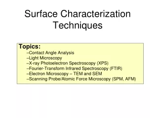
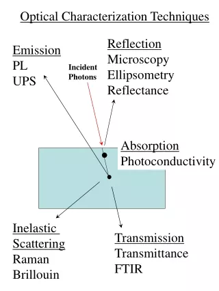
Chemical analysis of the surface • Basic determination of elements present at the surface • Determination of chemical bonding and atomic or molecular states in the surface region • Lateral and depth profiling of elemental distribution • XPS (X-ray photoelectron spectroscopy) • UPS (ultraviolet photoelectron spectroscopy) • AES (Auger electron spectroscopy) • SIMS (secondary ion mass spectrometry) • FTIR (Fourier transform infrared spectroscopy), ATR (attenuated total reflectance spectroscopy), Raman
The scanning part of SPMs • Based on the piezoelectric effect: • Piezo Tri-Pods • Piezo-Tube-Scanners • Problems of these scanners are: • Hysteresis, creep • Aging • Cross-correlations between the individual axis • These are addressed by extensive calibration-functions or closed-loop-systems utilizing laser-interferrometry Piezo-tube scanner and sketch of a piezo tripod
AFM - interaction • Lennard-Jones potential is often cited • Consisting of a van-der-Waals and a Pauli-part • Distance-dependence of interaction is changed in case of nanoscale objects • Basic behavior, however, is comparable
Non-contact mode • Idea here is to sense the sample without touching it → essential in the context of most polymer and biological samples • Cantilever is operated close to its resonance frequency via a piezo actuator
Electron microscope techniques-Scanning Electron Microscope (SEM)Transmission Electron Microscope (TEM)
Electron sources Electron guns: • Various examples of gun design • Thermionic • Schottky • Field emission • Cathode material • Tungsten • Lanthanum hexaboride (LaB6) • Others… • Cathode material determines emission current density Energy scheme of various gun types
What kind of species are generated? Probe-sample interaction results in the „generation“ of • Secondary electrons • Backscattered electrons • X-rays • Auger electrons • Plasmons
Secondary electrons (SE) • SE (exit energies < 50 eV) are generated if the energy gain of these species is large enough to overcome the work function • This process needs to be treated quantum mechanically as the scattering of an electron wave at a potential barrier • SE are only able to escape from a small surface range (probability of escaping is based on their inelastic mean free path) • Backscattered electrons contribute to the SE yield
Backscattered electrons (BSE) • BSE are present in the whole energy range from 50 eV (definition) to the maximum acceleration energy of the primary electrons (PE) • Their spectrum shows a broad peak overlapped by SE and Auger peaks as well as plasmon loss • BSE and SE are the most important signals for imaging. Knowledge about the dependence of the backscattering coefficient and the SE yield on surface tilt, material and electron energy is essential for any interpretation.
X-ray • Acceleration of a charged particle (electron) in the screened Coulomb potential of the nucleus leads – with a low probability – to an emission of a X-ray quantum (usually elastic scattering is observed) • Electron is decelerated by h (energy of the X-ray quantum) → continuous X-ray spectrum • This continuous spectrum is superposed on the characteristic X-ray spectrum generated by filling of inner shell vacancies
Diffraction based techniques-X-ray, neutron, and electron based methods
Basic definition of diffraction • Diffraction is the bending, spreading and interference of waves when they pass by an obstruction or through a gap. It occurs with any type of wave, including sound waves, water waves, electromagnetic waves such as light and radio waves, and matter displaying wave-like properties according to the wave–particle duality. Thomas Young (1773-1829), ophthalmologist and physicist Thomas Young's sketch of two-slit diffraction, which he presented to the Royal Society in 1803
X-ray sources Energy regime of Gamma- und X-ray radiation overlap – naming criteria is the heritage: X-ray is created by electron processes whereas Gamma radiation is a nuclear reaction product Typically X-ray radiation is generated by deceleration of electrons
X-ray sources (Synchrotron) Synchrotron radiation is emitted by charged relativistic particles deflected by a magnetic field tangentially to their path of motion In order to generate synchrotron radiation so called storage rings are used that keep the kinetic energy of the charged particles constant in order to conserve a constant energy spectrum of the radiation Worldwide, about 30 laboratories are able to generate synchrotron radiation. In Germany there are, among others, BESSY in Berlin, HASYLAB in Hamburg, DELTA at Universität Dortmund and ANKA in Karlsruhe A known natural source of synchrotron radiation is for example Jupiter which bombards its moons with synchrotron radiation
Neutron sources • Nuclear reactor • Usually fission reactors are used to generate kinetic neutrons to serve in diffraction experiments • Spallation source • Nuclear spallation is one of the processes by which a particle accelerator may be used to produce a beam of neutrons. A mercury, tantalum or other heavy metal target is used, and 20 to 30 neutrons are expelled after each impact of a high energy proton. Although this is a far more expensive way of producing neutron beams than by a chain reaction of nuclear fission in a nuclear reactor, it has the advantage that the beam can be pulsed with relative ease.
Bragg relation • The diffraction equation postulated by Bragg and his son in 1914 (Nobel laureate in 1915) Waves that satisfy this condition interfere constructively and result in a reflected wave of significant intensity
X-ray diffraction – phase analysis Rietveld method (Hugo Rietveld (1932-) allows a quantitative phase analysis in the context of X-ray and neutron diffractogramms • Analysis of the whole diffractogramm • Refinement of structure- as well as real-structure-parameters • Quantitative phase analysis • Lattice parameters and temperature effects • Grain size and micro strain • Its not a structure analysis! • Basic lattice parameters, • phase composition, and • Space group needs to be known Hugo Rietveld
Raman spectroscopy • The phenomenon behind this technique was first reported by Sir Chandrasekhara Venkata Raman (1888-1970) in 1928 – in 1930 he was awarded the Nobel Prize in physics for his findings • A small percentage of light scattered at a molecule is inelastically scattered (1 in 107 photons) Sir C.V. Raman
Raman spectroscopy - basics • At room temperature majority of molecules in initial (ground) state anti-Stokes signal will be less pronounced: Ratio of anti-Stokes to Stokes can be used for temperature measurement • The energy of a vibrational mode depends on molecular structure and environment. Atomic mass, bond order, molecular substituents, molecular geometry and hydrogen bonding all effect the vibrational force constant which, in turn dictates the vibrational energy • Vibrational Raman spectroscopy is not limited to intramolecular vibrations. Crystal lattice vibrations and other motions of extended solids are Raman-active • Raman scattering occurs when it features a change in polarizability during the vibration • This rule is analogous to the rule for an infrared-active vibration (that there must be a net change in permanent dipole moment during the vibration) - from group theory it is possible to show that if a molecule has a center of symmetry, vibrations which are Raman-active will be silent in the infrared, and vice versa
IR = Change in dipole of molecule Raman = Polarizability of Molecules Extended Equilibrium Compressed Raman spectroscopy vs. IR
Raman spectroscopy - examples • The frequency of the RBS mode is inversely proportional to the diameter of the nanotube • RBS mode and double peaked high energy modes are prove of the existence of single-wall nanotubes in a sample • In metallic carbon nanotubes the lower high-energy mode is strongly broadened and shifted to smaller energies (1540 cm-1) http://www-g.eng.cam.ac.uk/edm/research/ramanlab/raman_CNTs.html