Download
1 / 27
280 likes | 301 Views
Learn about the different building-block circuits used in digital systems, including decoders, encoders, and code converters. Understand their functions, how to build them, and their practical features.

E N D
EGR 2131 Unit 8Encoders, Code Converters, and Comparators • Read Brown & Vranesic, Sections 6.3 to 6.5. • Homework #8 and Lab #8 due next week. • Quiz next week.
Review: Useful Building-Block Circuits • Here are some kinds of “building-block” circuits: • Adders Chapter 5 • Multipliers • Multiplexers • Decoders • Encoders Chapter 6 Combinational • Code converters • Comparators • Latches & Flip-flops • Registers • Shift registers Chapter 7 Sequential • Counters Completelydifferent!
Review: Some Representative Chips • Many of the chips in the 7400 series contain circuits listed on the previous slide. • In a sense these chips are obsolete, because new designs no longer use 7400-series chips. But these are typical of the kind of circuits that are still widely used as building blocks in digital systems. And tools like Quartus let you place “virtual” copies of these chips.
Review: Useful Building-Block Circuits (Continued) • For each type of circuit listed above, you should understand: • What that type of circuit does, and why it’s useful. • How you could build such a circuit out of gates. • Typical features found in practical circuits in each category.
Review: Decoders, Encoders, & Code Converters • Decoders convert a binary code into a single active output representing that code’s value. • Encoders generate a coded output from a single active input line. • Code converters take one input code (such as BCD) and convert it to another code (such as binary).
Encoder • A binary encoder accepts an active logic level on one of its inputs and converts it to a coded binary output. • Here’s the basic logic diagram of a 4-to-2 encoder. This encoder has an input for each decimal digit, and two outputs that represent the binary code for the active input digit. • The zero input is not connected because the outputs should all be LOW when that input is active.
Priority Encoder • To handle cases where more than one input is active, an encoder circuit must be more complex than the one we just looked at. • Most actual encoders are priority encoders: if more than one input is active, the encoder ignores all but the one with the highest decimal value.
Priority Encoder (Cont’d.) • Another feature often found on encoders is an additional output (z in the example below) that distinguishes the case where the 0 input is the only active input from the case where no inputs are active.
An Encoder Application: Keyboard Encoder Keyboard encoders are found on calculators, computers, and other devices with keypads.
Some 74xx Encoder Chips • 74148 8-to-3 encoder (“octal” encoder) • 74147 10-to-40 encoder (“BCD” encoder)
Choices in Quartus Quartus gives you many options: Generic muxes, decoders, and so on. Or muxes, decoders, and so on that have the same specific features as the ones in 74XX-series chips. Or muxes, decoders, and so on from the Library of Parameterized Modules that you can customize to have just the features that you want.
Choices in Quartus(Cont’d.) • The choices on the previous slide assumed that you’re using schematic entry to draw a diagram of your design. • Another alternative is to use text entry with VHDL. Later we’ll see how to write VHDL code to implement multiplexers, decoders, encoders, and so on.
Different Numeric Codes • Different codes exist for using 1s and 0s to represent positive integers: • Standard binary code • Example: In standard binary, 15 is 1111. • Binary-coded decimal (BCD) • Example: In BCD, 15 is 0001 0101.
Code Converters • If a digital system needs to handle numbers using two different codes, it needs circuitry to convert between the two codes. • Example of a code converter: • 74184 BCD-to-binary and binary-to-BCD converter • Another, more widely used, example is associated with 7-segment displays…
7-Segment Displays • Alarm clocks, stereos, and many other devices use 7-segment displays on their front panels to display numbers. • The seven segments in such a display are namedas shown here.
BCD-to-7-Segment Code Converter • A BCD-to-7-segment code converter takes four input bits representing a digit and produces the seven signals needed to light up that digit on a 7-segment display.
A 74xx BCD-to-7-Segment Code Converter • Data sheet: 7447 • Seven output pins to control the seven segments of a 7-segment display • The same as ato gon previous slide, except they’re active-low. That’s because most 7-segment displays, including the ones on the DE2-115 board, require a LOW to light up a segment. See page 37 in DE2-115 User Manual. • Four input pins for BCD code (the same as w0 to w3 on previous slide).
A 74xx BCD-to-7-Segment Code Converter (Cont’d.) • Also has an active-low lamp test input that lights up all the segments. • Also a ripple-blanking input and output to suppress leading or trailing zeroes.
Segment Names on the DE2-115 Board • An earlier slide said that the seven segments are named as shown here: • Almost everyone uses the names shown above, but the DE2-115 User Manual does not. It uses numbers instead of letters:
Different Numeric Codes • Different codes exist for using 1s and 0s to represent positive integers. • Standard binary code • Example: In standard binary, 15 is 1111. • Binary-coded decimal (BCD) • Example: In BCD, 15 is 0001 0101. • Gray code • Example: In Gray code, 15 is 1000.
Four-Bit Gray Code • The key feature of Gray code is that only one bit changes when we increase a number by one. • This is not true of standard binary.
Why is Gray Code Useful? • Gray code is used for rotary encoders that sense the angular position of a shaft or axle. • From Wikipedia article on rotary encoders: Standard 3-bit binary code: no good! 3-bit Gray code: better!
Review: Code Converters • If a digital system needs to handle numbers using two different codes, it needs circuitry to convert between the two codes. • So we might find ourselves needing to convert from binary code to Gray code or vice versa….
Textbook Example 6.28: Design a 3-Bit Binary to Gray Code Converter Equations from truth table Truth table Circuit The pattern seen here in the equations and circuit extends to an arbitrary number of bits.
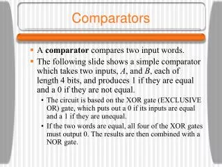
Comparator • A comparator compares the magnitudes of two binary numbers to determine the relationship between them. • In simplest form, a comparator can test for equality using XNOR gates. The output is high if and only if the 4-bit input numbers A and B are equal to each other.
Comparator (Cont’d.) • A more sophisticated comparator has three outputs instead of just one: • AeqB, which is high if and only if A and B are equal to each other. • AltB,which is high if and only if Ais less than B. • AgtB,which is high if and only if A is greater than B.
A 74xx Comparator Chip • 7485 Four-bit magnitude comparator