Download
1 / 34
340 likes | 586 Views
EET 1131 Unit 8 Code Converters, Multiplexers, and Demultiplexers. Read Kleitz, Chapter 8, skipping Sections 8-2 and 8-4. Homework #8 and Lab #8 due in a week and a half. Quiz when Homework #8 is due. Types of Chips. Here are the kinds of chips we’ll study in coming weeks: Comparators

E N D
EET 1131 Unit 8Code Converters, Multiplexers, and Demultiplexers • Read Kleitz, Chapter 8, skipping Sections 8-2 and 8-4. • Homework #8 and Lab #8 due in a week and a half. • Quiz when Homework #8 is due.
Types of Chips • Here are the kinds of chips we’ll study in coming weeks: • Comparators • Decoders • Encoders • Code converters • Multiplexers • Demultiplexers • Flip-flops • Counters • Shift registers • Multivibrators
Types of Chips (Continued) • For each type of chip listed on previous slide, you should understand: • What that type of chip does, and why it’s useful. • How you could build such a circuit out of gates. • Specific details of actual chips in each category.
Comparators The function of a comparator is to compare the magnitudes of two binary numbers to determine the relationship between them. In the simplest form, a comparator can test for equality using XNOR gates. How could you test two 4-bit numbers for equality? Example Solution AND the outputs of four XNOR gates. A1 B1 A2 B2 Output A3 B3 A4 B4
COMP A0 0 A1 A A2 A3 3 A > B A > B Cascading inputs A = B A = B A < B A < B B0 0 B B1 B2 B3 3 Comparators IC comparators provide outputs to indicate which of the input numbers is larger or if they are equal. Cascading inputs are provided to expand the comparator to larger numbers. Outputs The IC shown is the 4-bit 7485.
LSBs MSBs A0 A4 COMP COMP 0 0 A1 A5 A2 A6 A A A3 A7 3 3 A > B A > B A > B A > B +5.0 V Outputs A = B A = B A = B A = B A < B A < B A < B A < B B0 B4 0 0 B B B1 B5 B2 B6 B3 3 B7 3 Comparators IC comparators can be expanded using the cascading inputs as shown. The lowest order comparator has a HIGH on the A = B input.
Comparator Chip • 7485 Four-bit magnitude comparator
Enable Pins Many of the chips we’ll study have enable inputs. Depending on the logic level at this pin, the chip is either enabled or disabled. When the chip is enabled, it performs its intended function and the outputs behave as you would expect. When the chip is disabled, then (usually) all outputs are forced to their inactive state, regardless of the other inputs to the chip. Common names for enable pins include EN, G (for “gate”), and CS (for “chip select”).
Active-High versus Active-Low Pins • Each pin on a chip is either active-high or active-low. • In a logic symbol: • Active-low pins are marked with a bubble or triangle. • Active-high pins have no bubble or triangle. • Active-high pins: the pin is active when there’s a HIGH on that pin. • Many chips have active-low pins: the pin is active when there’s a LOW on that pin.
Example: 74154 Decoder From Floyd, p. 306 From Texas Instrument datasheet
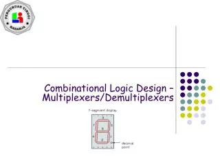
Decoders, Encoders, & Code Converters • Decoders convert a binary code into a single active output representing the code’s value. • Encoders generate a coded output from a single active input line. • Code converters take one input code (such as BCD) and convert it to another code (such as binary).
Decoders A decoder is a logic circuit that detects the presence of a specific combination of bits at its input. Two simple decoders that detect the presence of the binary code 0011 are shown. The first has an active HIGH output; the second has an active LOW output. A0 A0 X X A1 A1 A2 A2 A3 A3 Active HIGH decoder for 0011 Active LOW decoder for 0011
Decoders Assume the output of the decoder shown is a logic 1. What are the inputs to the decoder? Question
Decoders IC decoders have multiple outputs to decode any combination of inputs. For example the hex decoder shown here has 16 outputs – one for each combination of binary inputs. Question For the input shown, what is the output?
Decoders X/Y A specific integrated circuit decoder is the 74154, a 4-to-16 decoder. It includes two active LOW chip select lines which must be at the active level to enable the outputs. These lines can be used to expand the decoder to larger inputs. A0 A1 A2 A3 CS1 CS2 EN 74154
Octal Decoder • 3 data input pins for input code. • 8 output pins. • Also called 1-of-8 decoder or 3-line-to-8-line decoder. • May have other inputs and outputs too, such as enable inputs. • Example chip: 74138
Hex Decoder • 4 data input pins for input code. • 16 output pins. • Also called 1-of-16 decoder or 4-line-to-16-line decoder. • May have other inputs and outputs too, such as enable inputs. • Example chip: 74154
BCD Decoder • 4 data input pins for input code. • 10 output pins. • Also called 1-of-10 decoder or4-line-to-10-line decoder. • May have other inputs and outputs too, such as enable inputs. • Example chip: 74LS42
Encoders An encoder accepts an active logic level on one of its inputs and converts it to a coded output, such as BCD or binary. 1 The encoder has an input for each decimal digit and four outputs that represent the code for the active digit. The basic logic diagram is shown. There is no zero input because the outputs are all LOW when the input is zero. A0 2 3 A1 4 5 A2 6 7 8 A3 9
0 0 1 0 0 0 0 0 0 Encoders Show how the BCD encoder converts the decimal number 3 into a BCD 0011. Example The top two OR gates have ones as indicated with the red lines. Thus the output is 0011. Solution 1 1 A0 2 3 1 A1 4 0 5 A2 6 7 8 0 A3 9
Encoders The 74147 is an example of an IC encoder. It is has ten active-LOW inputs and converts the active input to an active-LOW BCD output. VCC This device offers additional flexibility in that it is a priority encoder. This means that if more than one input is active, the one with the highest order decimal digit will be active. HPRI/BCD Decimal input BCD output 74HC147 The next slide shows an application … GND
VCC Encoders Keyboard encoder HPRI/BCD BCD complement of key press 74HC147 The zero line is not needed by the encoder, but may be used by other circuits to detect a key press.
BCD Encoder • 10 input pins. • 4 output pins for output code. • Also called 10-line-to-4-line encoder. • May have other inputs and outputs too, such as enable inputs. • Example chip: 74147
Octal Encoder • 8 input pins. • 3 output pins for output code. • Also called 8-line-to-3-line encoder. • May have other inputs and outputs too, such as enable inputs. • Example chip: 74148
Different Numeric Codes • Several different codes exist for using 1s and 0s to represent positive integers. • Standard binary code • Example: In standard binary, 15 is 1111. • Binary-coded decimal (BCD) • Example: In BCD, 15 is 0001 0101. • Gray code • Example: In Gray code, 15 is 1000.
Four-Bit Gray Code • The key feature of Gray code is that only one bit changes when we increase a number by one. • This is not true of standard binary.
Why is Gray Code Useful? • Gray code is used for rotary encoders that sense the angular position of a shaft or axle. • From Wikipedia article on rotary encoders: Standard 3-bit binary code: no good! 3-bit Gray code: better!
Code Converters • A digital system may need to handle numbers using two different codes, in which case it needs circuitry to convert between the two codes. • Examples of code converters: • 74184 BCD-to-binary and binary-to-BCD converter • Binary-to-Gray code or Gray-code-to-binary converters (see next slide)
Gray Code/Binary Converters Figure 8-40. Binary-to-Gray-code converter Figure 8-41. Gray-code-to-binary converter
Multiplexers A multiplexer (MUX) selects one data line from two or more input lines and routes data from the selected line to the output. The particular data line that is selected is determined by the select inputs. Two select lines are shown here to choose any of the four data inputs. 0 Select inputs S0 1 S1 Data output D0 Question Data inputs D1 D2 Which data line is selected if S1S0 = 10? D3 D2
Some Multiplexer Chips • 74150 (16-input MUX) • 74151 (8-input MUX) • 74153 (dual 4-input MUX) • 74157 (quad 2-input MUX)
Demultiplexers A demultiplexer (DEMUX) performs the opposite function from a MUX. It switches data from one input line to two or more data lines depending on the select inputs. The 74LS138 was introduced previously as a decoder but can also serve as a DEMUX. When connected as a DEMUX, data is applied to one of the enable inputs, and routed to the selected output line depending on the select variables. Note that the outputs are active-LOW as illustrated in the following example… Data select lines Data outputs Enable inputs 74LS138
A 0 A Demultiplexers 1 A 2 Determine the outputs, given the inputs shown. Example G 1 LOW G Solution 2A LOW The output logic is opposite to the input because of the active-LOW convention. (Red shows the selected line). G 2B Y 0 Y 1 Data select lines Y 2 Y Data outputs 3 Y 4 Enable inputs Y 5 Y 6 Y 74LS138 7
Some Demultiplexer Chips • 74138(3-line to 8-line Decoder/DEMUX) • 74154(4-line to 16-line Decoder/DEMUX) • 74139(dual 2-line to 4-line Decoder/DEMUX)