Download
1 / 71
2.59k likes | 4.33k Views
Chapter 5: Active Filters. EMT 359/3 – Analog Electronic II. Outlines. Introduction Advantages of Active Filters over Passive Filters Types of filter Filter Response Characteristic Active Low-Pass Filter Active High-Pass Filter Active Band-Pass Filter Active Band-Stop Filter Summary.

E N D
Chapter 5:Active Filters EMT 359/3 – Analog Electronic II
Outlines • Introduction • Advantages of Active Filters over Passive Filters • Types of filter • Filter Response Characteristic • Active Low-Pass Filter • Active High-Pass Filter • Active Band-Pass Filter • Active Band-Stop Filter • Summary
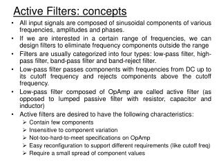
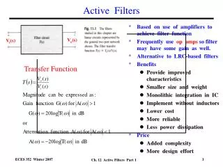
Introduction • Filters are circuits that are capable of passing signals within a band of frequencies while rejecting or blocking signals of frequencies outside this band. • This property of filters is also called “frequency selectivity”. • Passive filters - built using components such as resistors, capacitors and inductors. • Active filters - employ transistors or op-amps in addition to resistors and capacitors. • Active filters are mainly used in communication and signal processing circuits. • They are also employed in a wide range of applications such as entertainment, medical electronics, etc.
Advantages of Active Filters over Passive Filters • Active filters can be designed to provide required gain, and hence no attenuation as in the case of passive filters. • No loading problem, because of high input resistance and low output resistance of op-amp. • Active Filters are cost effective as a wide variety of economical op-amps are available.
Active Filter • There are 4 basic categories of active filters: • Low-Pass filters • High-Pass filters • Band-Pass filters • Band-Stop filters • Each of these filters can be built by using op-amp or transistor as the active element combined with RC, RL or RLC circuit as the passive elements.
Active Filter • The passband is the range of frequencies that are allowed to pass through the filter. • The critical frequency, fc is specified at the point where the response drops by 3 dB from the passband response (i.e. to 70.7% of the passband response) • The stopband is the range of frequencies that have the most attenuation • The transition regionis the area where the fall-off occurs
Low-Pass Filter • Allows the frequency from 0 Hz to critical frequency, fH (also known as cutoff frequency) • Ideally, the response drops abruptly at the critical frequency fH Ideal response Actual response
1st Order Low-Pass Filter • When • And
1st Order Low-Pass Filter • When • And is known as 3-dB or cutoff frequency (rad/s)
2nd Order Low-Pass Filter …(1) …(2) (1) & (2)
High-Pass Filter • Allows the frequencies above the critical frequency fL. (also known as the cutoff frequency. • Ideally, the response rises abruptly at the critical frequency. Ideal response Actual response
1st Order High-Pass Filter Where;
1st Order High-Pass Filter • When • When • When
1st & 2nd Order Filter Low-Pass Filter (LPF) High-Pass Filter
Band-Pass Filter • Allows frequencies between a lower cutoff frequency (fL) and an upper cutoff frequency (fH). Ideal response Actual response
Band-Pass Filter • Bandwidth (BW) • Center frequency • Quality factor (Q) is the ratio of center frequencyfo to the BW
Band-Stop Filter • Frequencies below fc1 (fL) and above fc2 (fH) are passed. Ideal response Actual response
Filter Response Characteristics • Identified by the shape of the response curve • Passband flatness • Attenuation of frequency outside the passband • Three types: 1. Butterworth 2. Bessel 3. Chebyshev
Filter Response Characteristics • Butterworth • Amplitude response is very flat in passband. • The roll-off rate -20 dB per decade (per filter order). • normally used when all frequencies in the passband must have the same gain. • Chebyshev • overshoot or ripples in the passband. • The roll-off rate greater than –20 dB. • can be implemented with fewer poles and less complex circuitry for a given roll-off rate. • Bessel • Linear phase response. • Ideal for filtering pulse waveforms.
Filter Response Characteristics Damping Factor • determines the type of response characteristic either Butterworth, Chebyshev, or Bessel. • The output signal is fed back into the filter circuit with negative feedback determined by the combination of R1 and R2
Filter Response Characteristics Critical Frequency • The critical frequency, fc is determined by the values of R and C in the frequency-selective RC circuit. • For a single-pole (first-order) filter, the critical frequency is: • The above formula can be used for both low-pass and high-pass filters
Filter Response Characteristics Roll-off rate • Greater roll-off rates can be achieved with more poles. • Each RC set of filter components represents a pole. • Cascading of filter circuits also increases the poles which results in a steeper roll-off. • Each pole represents a –20 dB/decade increase in roll-off
Filter Response Characteristics Roll-off depends on number of poles
Active High-Pass Filters • At critical frequency, Resistance = capacitive reactance critical frequency:
Active High-Pass Filters Roll-off depends on number of poles.
Active High-Pass Filters • A Single-Pole Filter
Active High-Pass Filters • The Sallen-Key • second-order (two-pole) filter • roll-off -40dB per decade Lets RA= RB= R and CA= CB= C;
Active High-Pass Filters At node V1:
Active High-Pass Filters ……(1) At node V2: ……(2) (2) in (1):
Active High-Pass Filters where = Damping Factor
Active High-Pass Filters • Cascaded HPF – Six pole • cascade 3 Sallen-Key two-pole stages • roll-off -120 dB per decade
Active Low-Pass Filters • At critical frequency, Resistance = capacitive reactance critical frequency:
Active Low-Pass Filters • A Single-Pole Filter
Active Low-Pass Filters • The Sallen-Key • second-order (two-pole) filter • roll-off -40dB per decade For RA= RB= R and CA= CB= C
Active Low-Pass Filters • The 3-dB frequency c is related to oby a factor known as the FREQUENCY CORRECTION FACTOR (kLP), thus; • Parameter table for Sellen-Key 2nd order LPF
Example Design a Bessel 2nd order low-pass filter with a 3-dB frequency of 5 kHz. Use C = 22 nF.
Solution • From the table: • Hence:
Solution • In order to minimize the offset error, we have to meet the following condition: • Or; • And: From the parameter table;
Solution A Bessel 2nd order LPF