Download
1 / 13
160 likes | 300 Views
Active Filters: concepts. All input signals are composed of sinusoidal components of various frequencies, amplitudes and phases. If we are interested in a certain range of frequencies, we can design filters to eliminate frequency components outside the range

E N D
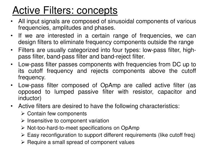
Active Filters: concepts • All input signals are composed of sinusoidal components of various frequencies, amplitudes and phases. • If we are interested in a certain range of frequencies, we can design filters to eliminate frequency components outside the range • Filters are usually categorized into four types: low-pass filter, high-pass filter, band-pass filter and band-reject filter. • Low-pass filter passes components with frequencies from DC up to its cutoff frequency and rejects components above the cutoff frequency. • Low-pass filter composed of OpAmp are called active filter (as opposed to lumped passive filter with resistor, capacitor and inductor) • Active filters are desired to have the following characteristics: • Contain few components • Insensitive to component variation • Not-too-hard-to-meet specifications on OpAmp • Easy reconfiguration to support different requirements (like cutoff freq) • Require a small spread of component values
Applications of Analog Filters • Analog filters can be found in almost every electronic circuit. • Audio systems use them for pre-amplification, equalization, and tone control. • In communication systems, filters are used for tuning in specific frequencies and eliminating others (for example, to filter out noise). • Digital signal processing systems use filters to prevent the aliasing of out-of-band noise and interference.
Butterworth low-pass filter • Many low-pass filter are designed to have a Butterworth transfer function with magnitude response as follows: Graphs from Prentice Hall
Low-pass filter: Sallen-Key Circuits • Active low-pass Butterworth filter can be implemented by cascading modified Sallen-Key circuits. • The Sallen-Key circuit itself is a 2nd order filter. To obtain an nth order filter, n/2 SK circuits should be cascaded • During design, capacitance • can be selected first and then • resistor values. • As K increase from 0 to 3, • the transfer function displays • more and more peaking. • It turns out that if K>3, then • the circuit is not stable. • Empirical values have been • found for filters of different • orders
Example of a 4th-order Lowpass filter by cascading two 2nd-order SK filters
Comparison of gain versus frequency for the stages of the fourth-order Butterworth low-pass filter.
Butterworth high-pass filter • By a change, the lowpass Butterworth transfer function can be transformed to a high-pass function.
Butterworth high-pass filter: Sallen-Key • By a change, the lowpass Butterworth transfer function can be transformed to a high-pass function. • With real OpAmp, the Sallen-Key is not truly a high-pass filter, because the gain of the OpAmp eventually falls off. However, the frequencies at which the OpAmp gain is fairly high, the circuit behaves as a high-pass filter. • Since the high-pass Sallen • Key circuit is equivalent the • same as the low-pass one, • the empirical values for K • would be still valid in this • case also.
Band-pass filter: Sallen-Key Circuits • If we need to design a band-pass filter in which the lower cutoff frequency is much less than the upper cutoff frequency, we can cascade a low-pass filter with a high-pass filter. • The below band-pass filter uses the first stage as a low-pass filter which passes frequency less than 10KHz and the second stage as a high-pass filter that passes only frequency above 100Hz. Thus, frequency components in-between is passed to the output. Graphs from Prentice Hall
Figure 11.11 Bode plots of gain magnitude for the active filter of Example 11.2.