Download
1 / 10
120 likes | 489 Views
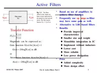
Active Filters. Dr. Holbert April 23, 2008. Active Filters. To achieve a gain > 1, we need to utilize an op-amp based circuit to form an active filter We can design all the common filter types using op-amp based active filters Recall for an ideal op-amp that V + = V – I + = I – = 0.

E N D
Active Filters Dr. Holbert April 23, 2008 EEE 202
Active Filters • To achieve a gain > 1, we need to utilize an op-amp based circuit to form an active filter • We can design all the common filter types using op-amp based active filters • Recall for an ideal op-amp that V+ = V– I+ = I– = 0 EEE 202
Op Amp Model V+ Non-inverting input + Rout Vo Rin + – – Inverting input A(V+ –V–) V– EEE 202
Non-inverting Op-Amp Circuit + – + + – Vin Z2 Vout Z1 – EEE 202
Inverting Op-Amp Circuit Z2 Z1 – – + – + Vin Vout + EEE 202
An Integrator C R – + – + + Vin Vout – Earlier in the semester, we saw this op-amp based integrator circuit. What type of filter does it create? Does this help you to understand time and frequency domain interrelations? EEE 202
A Differentiator R C – + – + + Vin Vout – We also observed this op-amp based differentiator circuit. What type of filtering does it produce? How could we move the zero away from the origin? EEE 202
Practical Example • You are shopping for a stereo system, and the following specifications are quoted: • Frequency range: –6 dB at 65 Hz and 22 kHz • Frequency response: 75 Hz to 20 kHz ±3 dB • What do these specs really mean? • Note that the human hearing range is around 20 Hz to 20 kHz (audible frequencies) • Could you draw a rough Bode (magnitude) plot for the stereo system? EEE 202
MATLAB Filter Example • How can we filter a real measurement signal? • One method involves using a numerical algorithm called the Fast Fourier Transform (FFT) which converts a time domain signal into the frequency domain • Start MATLAB, then download and run the ‘EEE202Filter.m’ file • Can you observe the reduction in the high frequency components in both the time and frequency domain plots of the output signal? EEE 202
MATLAB Filter Example (cont’d) • Can we extend the knowledge acquired about transfer functions and filtering? • How can we further reduce the high frequency component magnitudes? Show me. • How can we remove more high frequencies from the output signal? Show me. Input Signal Fast Fourier Transform Freq. Domain Filtering Inverse FFT Output Signal EEE 202