Download
1 / 33
330 likes | 384 Views
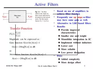
Test! OpAmp Active Filters. Q. What is v 0 ?. Filter. What is Active filter? What is Passive filter? What is analog filter? What is digital filter? An analog filter processes continuous-time signals A digital filter processes discrete-time signals. What is filter?

E N D
Filter • What is Active filter? • What is Passive filter? • What is analog filter? • What is digital filter? An analog filter processes continuous-time signals A digital filter processes discrete-time signals
What is filter? • Purpose of filter? • Types of filters? • What is cut-off frequency? • Draw frequency responses of 4 filters? • What is pass-band?
Pros and cons of active filter? • Pros and cons of passive filter?
Passive Filters • made up of passive components - resistors, capacitors and inductors • no amplifying elements (- transistors, op-amps, etc) • no signal gain • 1st order - design is simple (just use standard equations to find resonant frequency of the circuit) • 2nd order - complex equations • require no power supplies • not restricted by the bandwidth limitations of the op-amps • can be used at very high frequencies • can handle larger current or voltage levels than active devices • They are particularly non-ideal (lossy) • They are bulky and expensive EE3110 Active Filter (Part 1)
Passive elements : Inductor • high accuracy (1% or 2%), small physical size, or large inductance values are required?? • standard values of inductors are not very closely spaced • difficult to find an off-the-shelf inductor within 10 percent of any arbitrary value • adjustable inductors are used • tuning such inductors to the required values is time-consuming and expensive for larger quantities of filters • inductors are often prohibitively expensive EE3110 Active Filter (Part 1)
Active Filter • no inductors • made up of op-amps, resistors and capacitors • provides virtually any arbitrary gain • generally easier to design • high input impedance prevents excessive loading of the driving source • low output impedance prevents the filter from being affected by the load • at high frequencies is limited by the gain-bandwidth of the op-amps • easy to adjust over a wide frequency range without altering the desired response EE3110 Active Filter (Part 1)
Draw ideal filter responses of 4 types of filters. • Draw the same for practical filters.
Draw the Bessel characteristics of a LPF. • Draw the same for a HPF.
Bessel Characteristic • Flat response in the passband. • Phase response is linear. • Used for filtering pulse waveforms without distorting the shape of the waveform. EE3110 Active Filter (Part 1)
Butterworth Characteristic • Very flat amplitude, Av(dB) , response in the passband. • Phase response is not linear. • Used when all frequencies in the passband must have the same gain. • Often referred to as a maximally flat response. EE3110 Active Filter (Part 1)
Draw Chebyshev characteristic for LPF • Draw the same for BPF
Chebyshev Characteristic • Overshoot or ripples in the passband. • Role-off rate greater than 20dB/decade/pole. • Phase response is not linear - worse than Butterworth. • Used when a rapid roll-off is required. EE3110 Active Filter (Part 1)
Draw a passive LPF filter circuit. • Draw an active LPF filter circuit.
What is cut-off frequency for LPF? • What is ,,, for HPF? • What is ,,, for BPF? • What is ,,, for BRF?
dB/… • In many situations, the magnitude attenuation of a signal is given in units of dB/decade or dB/octave. • The decibel is defined in terms of a power (P) ratio, or the magnitude ratio (M). • A decade is defined as a 10-fold increase in frequency. • An octave is defined as a 2-fold increase (doubling) in frequency.
Two-Stage Band-Pass Filter BW = f2 – f1 Q = f0 / BW EE3110 Active Filter (Part 1)
Band-Stop (Notch) Filter The notch filter is designed to block all frequencies that fall within its bandwidth. The circuit is made up of a high pass filter, a low-pass filter and a summing amplifier. The summing amplifier will have an output that is equal to the sum of the filter output voltages. Frequency response Block diagram EE3110 Active Filter (Part 1)
Notch filter EE3110 Active Filter (Part 1)