Download
1 / 6
60 likes | 288 Views
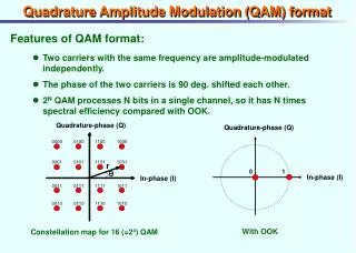
Prof. Brian L. Evans Dept. of Electrical and Computer Engineering The University of Texas at Austin. Quadrature Amplitude Modulation (QAM) Receiver. Introduction. Channel has linear distortion, additive noise, and nonlinear distortion

E N D
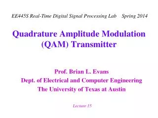
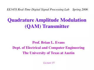
Prof. Brian L. Evans Dept. of Electrical and Computer Engineering The University of Texas at Austin Quadrature Amplitude Modulation (QAM) Receiver
Introduction • Channel has linear distortion, additive noise, and nonlinear distortion • Adaptive digital FIR filter used to equalize linear distortion (magnitude/phase distortion in channel) Channel equalizer coefficients adapted during modem startup At startup, transmitter sends known PN training sequence AGC Carrier Detect I(nT) X LPF r0(t) r1(t) r(t) r(nT) Receiver Filter A/D Q(nT) X LPF Symbol Clock Recovery 90o
QAM Receiver • Automatic gain control • Scales analog input voltage to appropriate level for A/D • Increase gain when received signal level is low • Carrier detection • Determines whether or not a QAM signal is present • Symbol clock recovery • Track clock frequency • In-phase/quadrature (I/Q) demodulation • Recover baseband in-phase/quadrature signal
Carrier Detection • If receiver is not currently receiving a signal, then it listens for known training sequence • Detect energy of received signal • c is a constant where 0 < c < 1 • r[n] is received signal • Check if received energy is larger than threshold • If receiver is currently receiving signal, then it detects when transmission has stopped • Detect energy of received signal • Check whether it is smaller than a smaller threshold Transfer function?
Symbol Clock Recovery • Two single-pole bandpass filters in parallel • One tuned to upper Nyquist frequency u = c + 0.5 sym • Other tuned to lower Nyquist frequency l = c– 0.5 sym • Bandwidth is B/2 (100 Hz for 2400 baud modem) • A recovery method • Multiply upper bandpass filter output with conjugate of lower bandpass filter output and take the imaginary value • Sample at symbol rate to estimate timing error • Smooth timing error estimate to compute phase advancement Pole locations? See Reader handout M when Lowpass IIR filter
In-Phase/Quadrature Demodulation • QAM transmit signal • QAM demodulation by modulation then filtering • Construct in-phase i(t) and quadrature q(t) signals • Lowpass filter them to obtain baseband signals a(t) and b(t) baseband high frequency component centered at 2 wc baseband high frequency component centered at 2 wc