Download
1 / 57
610 likes | 646 Views
Amplitude Modulation. Objectives: To introduce amplitude modulation To study double sideband suppressed carrier modulation (DSB-SC) systems To describe coherent demodulation method for amplitude modulation To assess the influence of carrier phase for coherent demodulation

E N D
Amplitude Modulation • Objectives: • To introduce amplitude modulation • To study double sideband suppressed carrier modulation (DSB-SC) systems • To describe coherent demodulation method for amplitude modulation • To assess the influence of carrier phase for coherent demodulation • To briefly explain single sideband modulation (SSB) systems • To study standard (conventional) amplitudemodulation (AM) systems • To introduce modulation index and illustrate its effect in AM • To describe envelope demodulation in AM system • To calculate sideband power, carrier power and transmission efficiency in AM • To assess the noise performance in amplitude modulation systems • To compare the performance in different amplitude modulation systems
Amplitude Modulation Recall that Modulation is the process by which a parameter of a carried wave is varied in proportion to a signal. Types of analog modulation A carrier wave is given by Acos(ct + ) Three parameters: Amplitude A, Frequency c (angular frequency), Phase . The modulation process is termed as amplitude modulation, frequency modulation, or phase modulation.
Amplitude Modulation Baseband communications systems • Characteristics of baseband communication systems: • The signal is transmitted directly without any modulation. • Simple system, but not widely used, mainly used in short-haul system.
Amplitude Modulation Double sideband suppressed carrier modulation (DSB-SC) systems From modulation theorem if g(t) G() then g(t)cos(ct) (1/2)[G( + c) + G( - c)] DSB-SC signal generation Waveform: sDSB-SC(t) = m(t)cosct Spectrum:SDSB-SC() = (1/2)[M( + c) + M( - c)]
Amplitude Modulation Principle of coherent demodulation method: Multiplying the signal m(t)cosct by a local carrier wave cosct e(t) = m(t)cos2ct = (1/2)[m(t) + m(t)cos2ct] E() = (1/2)M() + (1/4)[M( + 2c) + M( - 2c)] Passing through a low pass filter: So() = (1/2)M() The output signal: so(t) = (1/2)m(t)
Amplitude Modulation Operating principle of DSB-SC system:
Amplitude Modulation Example: Tone modulation In tone modulation, the modulation signal is a pure sinusoidal, cosmt. Signal m(t) = cosmt Signal spectrum[( + m) + ( - m)] DSB-SC signal waveform sDSB-SC(t) = cosmt cosct = (1/2)[cos(c + m)t + cos(c - m)t] DSB-SC signal spectrum SDSB-SC() = (/2)[( + c + m) + ( + c - m) + ( - c + m) + ( - c - m)]
Amplitude Modulation When modulated signal multiplied by cosct, then e(t) = cosmt cos2ct = (1/2)cosmt (1 + cos2ct) = (1/2)cosmt + (1/2)cosmt cos2ct Spectrum of e(t) E() = (/2)[( + m) + ( - m)] + (/4)[( + 2c + m) + ( + 2c - m) + ( - 2c + m) + ( - 2c - m)] The output signal spectrum after being suppressed by a low pass filter So() = (/2)[( + m) + ( - m)] Output signal waveform so(t) = (1/2)cosmt
Amplitude Modulation Diagram
Amplitude Modulation The spectrum of the modulated signal consists of frequency components at c + m and c - m, there is no component at carrier frequency, this is why the name suppressed carrier is used.
Amplitude Modulation • The demodulation process in a DSB-SC system: • Multiplying the modulated signal by a local carrier of the • same frequency and phase • with the carrier at the modulator. • 2. The product obtained is then passed through a low pass filter in order to recover the signal. • This task is difficult to achieve or quite expensive. • (Why?)
Amplitude Modulation Influence of carrier phase for coherent demodulation DSB-SC signal: sDSB-SC(t) = m(t)cosct Local carrier wave: cos[(c + c)t + ] Where c is the frequency error and is the phase error. The output from the multiplier : m(t)cosct cos[(c + c)t + ] = (1/2)m(t){cos[(2c + c)t + ] + cos(ct + )} The output from the low-pass filter : s(t) = (1/2)m(t)cos(ct + )
Amplitude Modulation When c = 0, only phase error exists, s(t) = (1/2)m(t)cos If = /2, s(t) = 0, there is no component in the output corresponding to the message. Furthermore, if varies with time, s(t) will appear as the noise. When = 0, only frequency error c exists, s(t) = (1/2)m(t)cosct The message is modified by a low frequency sinusoidal wave cosct (although c is high, c is usually low), it will be attenuated and distorted.
Amplitude Modulation Disadvantages of DSB-SC: 1. It transmits both sidebands which contain identical information and thus waste the channel bandwidth resources; 2. It requires a fairly complicated (expensive) circuitry at a remotely located receiver in order to avoid phase errors.
Amplitude Modulation Single sideband modulation (SSB) The DSB-SC spectrum contains the upper sideband (USB) and the lower sideband (LSB), both containing the same information. SSB solves the first disadvantage from which DSB-SC suffers by using a highpass filter at the output of the modulator so that either the upper sideband or the lower one is filtered out before transmission. Lower the bandwidth of the modulated signal can increase the number of channels.
Amplitude Modulation It is desirable to transmit only one sideband. This creates single sideband modulation (SSB). SSB signal generation The most straightforward way to generate an SSB signal is to first generate a DSB signal and then suppress one of the sidebands by filtering. The primary difficulty of this method is to meet the filter requirement.
Amplitude Modulation Single sideband modulation (SSB)
Amplitude Modulation Standard (conventional) amplitude modulation (AM) The disadvantage of high cost receiver circuit of the DSB-SC system can be solved by use of AM, but at the price of a less efficient transmitter. An AM system transmits a large power carrier wave, Acosct, along with the modulated signal, m(t)cosct, so that there is no need to generate a carrier at the receiver. Advantage : simple and low cost receiver In a broadcast system, the transmitter is associated with a large number of low cost receivers. The AM system is therefore preferred for this type of application.
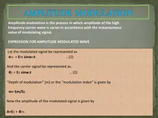
Amplitude Modulation AM signal generation Waveform : sAM(t) = Acosct + m(t)cosct = [A + m(t)]cosct Spectrum : SAM() = (1/2)[M( + c) + M( - c)] + A[( + m) + ( - m)]
Amplitude Modulation The amplitude modulated signal, sAM(t) = [A + m(t)]cosct may be regards as a carrier signal cosct whose amplitude is given by the quantity [A + m(t)], i.e. message + dc component. If the message + dc component is positive, the envelop of the modulated signal then has the same shape as the message, m(t), and the demodulation can be carried out by the detection of the envelope of the carrier, with no dependence on the exact phase or frequency of the the carrier. However, if A is not large enough, the envelope of the amplitude modulated signal is not always proportional to m(t).
Amplitude Modulation Condition for distortionless modulation A + m(t) 0 or A m(t)max If above condition is not satisfied, the m(t) cannot be recovered by the envelope detection, but we can still use coherent detection method.
Amplitude Modulation Modulation index m = m(t)max / A The message signal, m(t), is preserved in the envelope of the AM signal only if m(t)max A, i.e. m = m(t)max / A 1 (1) When m < 1, then m(t)max < A, the envelope is not reaching the zero-amplitude axis of the AM wave. An envelope detector can recover the message signal without distortion. (2) When m = 1, then m(t)max = A, the waveform envelope just touches the zero-amplitude axis. A small variation in the magnitude of m(t) will cause envelope distortion.
Amplitude Modulation (3) When m > 1, then m(t)max > A, portion of the envelope crosses the zero-amplitude axis, positive and negative excursions canceling each other. This situation is called overmodulation. An envelope detector will provide distorted message signal. A portion of the detected message signal is clipped. A message signal can be recovered from AM signal by using a less costly and simple envelope detector, provided that m 1. However, an overmodulatedsignal can be recovered using a costly and complex technique: synchronous (coherent) detection.
Amplitude Modulation Example Show that an AM signal can be recovered, irrespective of the value of percentage modulation by using synchronous detection technique. Solution sAM(t) = Acosct + m(t)cosct = [A + m(t)]cosct In coherent detection, sAM(t) is multiplied by cosct and then passed through a low-pass filter.
Amplitude Modulation Multiplication with cosct yields sAM(t)cosct = [A + m(t)]cos2ct = (1/2)[A + m(t)]( 1 + cos2ct) = A/2 + m(t)/2 + (1/2)[A+ m(t)]cos2ct After passing through a low-pass filter, the terms centered around at 2ct are filtered out, so(t) = (1/2)[A + m(t)] the constant A/2 can be removed by a capacitor and hence we are able to recover the baseband signal m(t). Even overmodulated signal can be recovered using a synchronous detection, however, the price paid is a complicated circuitry.
Amplitude Modulation Experimental determination of modulation index The modulation index can be determined experimentally by observing the AM waveform on an oscilloscope By definition, m = Em / Ec, from Em = (1/2)(Emax – Emin) and Ec = Emin + Em = Emin + (1/2)(Emax – Emin) = (1/2)(Emax + Emin) so that m = (Emax – Emin) / (Emax + Emin)
Amplitude Modulation Envelop detector The simplest envelope detector is a nonlinear charging circuit with a fast charge time and a slow discharge time. It can easily be constructed using a diode in series with a capacitor.
Amplitude Modulation The operation of the envelope detector: During the positive half-cycles of the input signal, C is charged to the peak value. As the input signal falls below its maximum, the diode turns off. A slow discharge of the capacitor through the resistor begins until the next positive half-cycle when the diode turns on again. If the RC value is too large, the envelope detector may miss some positive half-cycles of the carrier. If the RC value is too small, the envelope detector generates a very ragged waveform, losing some of its efficiency. The envelope detector is simple, efficient, and cheap to build.
Amplitude Modulation Simple envelop detector In an envelope detection circuit, a diode removes the negative part of the modulated signal, whereas the filter removes the carrier. The dc term is eliminated by using ac coupling. (AC coupling uses a capacitor to block the dc current).
Amplitude Modulation Carrier and sideband power in AM In AM signal waveforms, the carrier terms does not contain any information about the signal m(t). Therefore the power expended in this carrier is wasted for any transfer of information. A general AM signal waveform sAM(t) = Acosct + m(t)cosct The total average power of sAM(t) It is assumed that the average value of m(t) is zero (the usual case)
Amplitude Modulation Total power can be expressed as the sum of the carrier power, Pc, and sideband power, Ps. Carrier power Sideband power The transmission efficiency of AM signal The amount of useful message power present in AM wave is expressed by a term called transmission efficiency.
Amplitude Modulation ExampleTone modulation Message signal m(t) = Amcosmt AM signal sAM(t) = Acosct + m(t)cosct = Acosct + Amcosmtcosct =A[1 + (Am/A) cosmt]cosct = A(1 + m cosmt)cosct = Acosct + m A cosmtcosct we have Because m 1, the transmission efficiency of an AM system is at best 33%.
Amplitude Modulation Example A given AM braoadcast station transmits an average carrier power output of 40 kW and uses a modulation index of 0.707 for sine wave modulation. Calculate (a) the total average power output ; (b) the transmission efficiency ; and (c) the peak amplitude of output if the antenna is represented by a 50 resistive load. Solution Pt = Pc(1 + m2/2) For m = 0.707, Pt = Pc(1 + 1/4) = (5/4)Pc = (5/4) 40 = 50 kW Pc = A2 / 2R, A2 = 2RPc = 4 106 (1 + m)A = 3414 V
Amplitude Modulation In order to determine the signal-to-noise (SNR), we have to consider the noise effect in the communication system. Communication in the presence of noise In communication systems, message signal travels from the transmitter to the receiver via a channel. The channel introduces additive noise in the message and, hence, the message reaching the receiver becomes corrupted. The receiver detects both noise and message signals, it reproduces a noisy message at the output.
Amplitude Modulation In a communication system, the noise introduced by the transmission channel is considered as white noise.
Amplitude Modulation White noise White noise is noise whose power spectral density is uniformover the entire the frequency range. The term white is used in analogy with white light, which is a superposition of all visible spectral components. Sn() = / 2 Where is a constant.
Angle Modulation Baseband system The baseband signal is assumed to be band limited and the channel be distortionless, then The output signal power: The output noise power The output SNR for the baseband system:
Angle Modulation SNR for DSB and SSB transmission It can be shown that: SNR for AM (with a large carrier)
Amplitude Modulation • Comparison of various AM systems • Receiver end • Standard AM (large carrier) system: • Simple and inexpensive envelope detectors. • Preferably used in public communication systems where a transmitter is associated with a large number of receivers. • Suppressed carrier system: • Complex and high cost as they need additional synchronizing circuits.
Amplitude Modulation • Transmitter end • Suppressed carrier system: • Low power transmitters are needed as no carrier power is transmitted. • The low power transmitters are less expensive than the large power AM transmitters. • Useful in point to point communication where we need many transmitters but only few receivers per transmitter. • Generation of modulated signals • SSB-SC is more difficult to generate than DSB-SC.
Amplitude Modulation • Bandwidth • SSB-SC system: • Message bandwidth. • Used in long-range high-frequency communications, especially in audio communication, where phase-distortion is not significant. • DSB-SC and standard AM systems: • Twice message bandwidth. • Transmission efficiency • Suppressed carrier system: 100% • Standard AM system: the maximum efficiency is only 33.3%, corresponding to m = 1.
Amplitude Modulation • Noise performance • SSB-SC and DSB-SC systems: • The same output signal-to-noise ratio as baseband system. • The standard AM system (with a large carrier): • Reduced output signal-to-noise ratio when compared with baseband system.
Amplitude Modulation • Conclusion • Each type of amplitude has its advantages and disadvantages. • Each circumstance must be evaluated on its own merits and the choice of modulation tailored to that situation.
Questions (Amplitude Modulation) • Name three parameters of the carrier that can be varied to produce modulation. • Define amplitude modulation. • Is the signal modulated when it transmits through a baseband communication system? • How to generate a DSB-SC signal? • Draw a time-domain and frequency-domain picture of a DSB-SC signal. • What is the demodulation method for DSB-SC signal? • What is tone modulation? • What is the influence of carrier phase for coherent demodulation? • What are the key advantages offered by AM over DSB-SC?
Questions (Amplitude Modulation) 10.What is the condition for distortionless modulation? 11. Define modulation index. 12. Explain why 100% modulation is not an ideal value. 13. Define overmodulation. 14. What happens to the modulation index of an AM signal if the carrier level remains constant and the sideband level increases? 15. How to determine the modulation index experimentally? 16. What is the main demodulation method used for standard AM signal? 17. Write the expression of transmission efficiency for AM signal. 18. What is the merit of SSB-SC system? 19. What is white noise? 20. Compare the characteristics of various AM systems.
Exercise Problems (Amplitude Modulation) • 1. An AM voltage signal consists of a carrier wave 100cos(2 106t) and a DSB-SC signal (20cos6.28t + 50cos12.56t) cos(2 106t), • (a) Draw the spectrum of the modulated message; • (b) Determine the carrier power, sideband power and the total power of the modulated signal. • 2. An AM transmitter has a carrier power of 30W. The message signal is a sinusoidal signal and the percentage of modulation is 85%, i.e. m = 0.85. Calculate: • the total power; and • (b) the power in one sideband.
Exercise Problems (Amplitude Modulation) 3. For DSB-SC modulation, m(t) = 4 + 2cos(2 103t), carrier wave xc(t) = 8cos(2 106t) (a) Draw the frequency domain representation of m(t), xc(t) and the modulation output x(t); (b) Draw the block diagram of the demodulation system diagram, if low pass filter is used in the demodulator, what is the minimum bandwidth required to fully recover the signal? (c) What is the frequency and time domain representation of the demodulation output?
Exercise Problems (Amplitude Modulation) 4. The figure below shows an amplitude modulator. Assuming sinusoidal carrier xc(t) and sinusoidal message signal m(t), i.e., xc(t) = Accosct, m(t) = Amcosmt The modulated signal x(t) can be written as x(t) = Ac[1 + (Am/Ac)cosmt]cosct (a) For Am = Ac, calculate the modulation index; (b) Determine the fraction of total transmitted power concentrated in the modulation sideband for(1) Am = Ac; (2) Am = Ac/2;(3) Am = aAc, where a < 1;
Exercise Problems (Amplitude Modulation) 5. To prove that the following system can be used for AM signal demodulation and the bandwidth of the low-pass filter must be 2Wm, where Wm is the highest frequency of the message signal.