Download
1 / 30
570 likes | 1.26k Views
Amplitude Modulation. Wei Li weili@ieee.org. Content. What is Modulation Amplitude Modulation (AM) Demodulation of AM signals Calculation and Examples Summary. What is Modulation. Modulation

E N D
Amplitude Modulation Wei Li weili@ieee.org CSULB May 22, 2006
Content • What is Modulation • Amplitude Modulation (AM) • Demodulation of AM signals • Calculation and Examples • Summary CSULB May 22, 2006
What is Modulation • Modulation • In the modulation process, some characteristic of a high-frequency carrier signal (bandpass), is changed according to the instantaneous amplitude of the information (baseband) signal. • Why Modulation • Suitable for signal transmission (distance…etc) • Multiple signals transmitted on the same channel • Capacitive or inductive devices require high frequency AC input (carrier) to operate. • Stability and noise rejection CSULB May 22, 2006
About Modulation • Application Examples • broadcasting of both audio and video signals. • Mobile radio communications, such as cell phone. • Basic Modulation Types • Amplitude Modulation: changes the amplitude. • Frequency Modulation: changes the frequency. • Phase Modulation: changes the phase. CSULB May 22, 2006
AM Modulation/Demodulation Source Sink Channel Modulator Demodulator Baseband Signal with frequency fm (Modulating Signal) Bandpass Signal with frequency fc (Modulated Signal) Original Signal with frequency fm fc >> fm Voice: 300-3400Hz GSM Cell phone: 900/1800MHz CSULB May 22, 2006
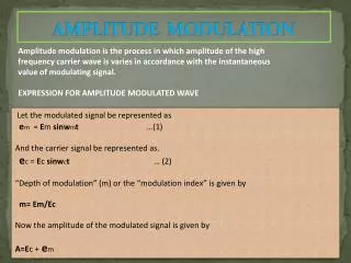
Amplitude Modulation • The amplitude of high-carrier signal is varied according to the instantaneous amplitude of the modulating message signal m(t). CSULB May 22, 2006
* AM Signal Math Expression* • Mathematical expression for AM: time domain • expanding this produces: • In the frequency domain this gives: Carrier, A=1. k/2 Amplitude k/2 frequency fc fc-fm fc+fm lower sideband upper sideband CSULB May 22, 2006
AM Power Frequency Spectrum • AM Power frequency spectrum obtained by squaring the amplitude: • Total power for AM: Carrier, A2=12 = 1 Power k2/4 k2/4 fc+fm fc-fm fc freq . CSULB May 22, 2006
Amplitude Modulation • The AM signal is generated using a multiplier. • All info is carried in the amplitude of the carrier, AM carrier signal has time-varying envelope. • In frequency domain the AM waveform are the lower-side frequency/band (fc - fm), the carrier frequency fc, the upper-side frequency/band (fc + fm). CSULB May 22, 2006
AM Modulation – Example • The information signal is usually not a single frequency but a range of frequencies (band). For example, frequencies from 20Hz to 15KHz. If we use a carrier of 1.4MHz, what will be the AM spectrum? • In frequency domain the AM waveform are the lower-side frequency/band (fc - fm), the carrier frequency fc, the upper-side frequency/band (fc + fm). Bandwidth: 2x(25K-20)Hz. 1.4 MHz frequency fc 1,400,020Hz to 1,415,000Hz 1,385,000Hz to 1,399,980Hz CSULB May 22, 2006
Modulation Index of AM Signal For a sinusoidal message signal Modulation Index is defined as: Modulation index k is a measure of the extent to which a carrier voltage is varied by the modulating signal. When k=0 no modulation, when k=1 100% modulation, when k>1 over modulation. CSULB May 22, 2006
Modulation Index of AM Signal CSULB May 22, 2006
Modulation Index of AM Signal CSULB May 22, 2006
Modulation Index of AM Signal CSULB May 22, 2006
Modulation Depth 2Amax = maximum peak-to-peak of waveform 2Amin = minimum peak-to-peak of waveform as follows: This may be shown to equal Am Ac 2Amax 2Amin CSULB May 22, 2006
High Percentage Modulation • It is important to use as high percentage of modulation as possible (k=1) while ensuring that over modulation (k>1) does not occur. • The sidebands contain the information and have maximum power at 100% modulation. • Useful equation Pt = Pc(1 + k2/2) Pt =Total transmitted power (sidebands and carrier) Pc = Carrier power CSULB May 22, 2006
Example • Determine the maximum sideband power if the carrier output is 1 kW and calculate the total maximum transmitted power. • Max sideband power occurs when k = 1. At this percentage modulation each side frequency is ½ of the carrier amplitude. Since power is proportional to the square of the voltage, each has ¼ of the carrier power. ¼ x 1kW = 250W Total sideband power = 2 x 250 = 500W. Total transmitted power = 1kW + 500W = 1.5kW CSULB May 22, 2006
Demodulation of AM Signals • Demodulation extracting the baseband message from the carrier. • There are 2 main methods of AM Demodulation: • Envelope or non-coherent detection or demodulation. • Synchronised or coherent demodulation. CSULB May 22, 2006
Envelope/Diode AM Detector If the modulation depth is > 1, the distortion below occurs K>1 CSULB May 22, 2006
Synchronous or Coherent Demodulation This is relatively more complex and more expensive. The Local Oscillator (LO) must be synchronised or coherent, i.e. at the same frequency and in phase with the carrier in the AM input signal. CSULB May 22, 2006
Synchronous or Coherent Demodulation If the AM input contains carrier frequency, the LO or synchronous carrier may be derived from the AM input. CSULB May 22, 2006
Synchronous or Coherent Demodulation If we assume zero path delay between the modulator and demodulator, then the ideal LO signal is cos(ct). Analysing this for a AM input = CSULB May 22, 2006
Coherent Detection Assume zero path delay between the modulator and demodulator: VX = AM input x LO = = = Note – the AM input has been 'split into two' – ‘red part' has moved or shifted up to higher frequency: and blue part shifted down to baseband: CSULB May 22, 2006
Coherent Detection CSULB May 22, 2006
Diode v.s Coherent • Diode-: Unable to follow fast-modulation properly • Diode-: Power is absorbed from the tuned circuit by the diode circuit. • Diode-: Distortion produced is not acceptable for some communications. • Diode+: Obviously simple, low cost. • Coherent+: Low Distortion • Coherent+: Greater ability to follow fast-modulation. • Coherent+: The ability to provide power gain • Coherent-: Complex and expensive CSULB May 22, 2006
Exercises: Draw the Spectrums a) cos(wct)cos(w1t) from cosAcosB= 1/2[cos(A-B)+cos(A+B)] we get: cos(wct)cos(w1t)=1/2[cos(wc-w1)t + cos(wc+w1)t] Hence the spectrum of this is: b) cos2wt from cos2A=1/2[1+cos2A] we get: cos2wt=1/2[1+cos2wt] The spectrum is thus: amplitude 1/2 1/2 wc-w1 wc+w1 frequency 1/2 1/2 DC=0Hz 2w freq CSULB May 22, 2006
Example Suppose you have a portable (for example you carry it in your ' back pack') AM transmitter which needs to transmit an average power of 10 Watts in each sideband when modulation depth k = 0.3. Assume that the transmitter is powered by a 12 Volt battery. The total power will be where Hence, total power PT = 444.44 + 10 + 10 = 464.44 Watts. Hence, battery current (assuming ideal transmitter) = Power / Volts = A large and heavy 12 Volt battery!!!! Suppose we could remove one sideband and the carrier, power transmitted would be 10 Watts, i.e. 0.833 amps from a 12 Volt battery, which is more reasonable for a portable radio transmitter. (Single Side Band) CSULB May 22, 2006
AM Transmitter and Receiver CSULB May 22, 2006
AM Transmitter and Receiver CSULB May 22, 2006
Summary • Modulation, Amplitude Modulation • Modulation Index, Modulation Depth • Demodulation of AM signals • Calculation and Examples • Math: AM Time domain+Frequency domain • Calculation: AM Power, AM Demodulation Next Class…. • DSB, SSB, VSB…… • FM, PM CSULB May 22, 2006