Download
1 / 15
150 likes | 341 Views
IBL MoU. ATLAS Upgrade Week DESY, April 24 th 2010 M. Nordberg, M. Nessi, C. Gößling, H. Pernegger Presented by: G. Darbo - INFN / Genova Indico agenda page: http://indico.cern.ch/conferenceOtherViews.py?view=standard&confId=75714. IBL Detector. Material from Raphael/Neal.

E N D
IBL MoU ATLAS Upgrade Week DESY, April 24th 2010 M. Nordberg, M. Nessi, C. Gößling, H. Pernegger Presented by: G. Darbo - INFN / Genova Indico agenda page: http://indico.cern.ch/conferenceOtherViews.py?view=standard&confId=75714
IBL Detector • Material from Raphael/Neal • The present 7m long section of the beam-pipe will be cut (flange too big to pass inside the existing pixel) and extracted in situ: • The new beam-pipe with the IBL will be inserted at its place. PP1 Collar Sealing service ring Alignment wirers Iourii Gusakov IST IBL Support Tube IBL Staves Existing B-layer IBL (Staves)
From BL Replacement to IBL Project • The Pixel B-Layer (BL) was considered a replaceable component since the original Pixel TDR (1998) due to the limited radiation hard of the design: • BL qualified for 50 Mrad and 1x10¹⁵ 1 MeV n/cm2 300 fb-1 at R=5 cm • BL was also included in the Pixel M&O-B tables in 2002 (this cost was considered to be 4.4 MCH) • In Sept 2007 Pixel Collaboration realised that the BL is not replaceable: • Long time (detector has to be brought to surface): disconnect/reconnect of services, major dismounting of internal services to get access to BL removal, long work on activated detector, risk of major damage (last moment fixed not documented). • Task Force (A. Clark, G. Mornacchi – Jan/Jun 2008) – Motivation for replacement: • Total dose: Pixel BL cannot stand full life dose of LHC (LHC designed for 730 fb-1). • Hard Pixel failures: B-Layer is the most important/fundamentat layer for vertexing and B-tagging. • Improve Physics performance of existing ID (goal ~1/2 of X/X0 of BL) • Best (only) option an Insertable B-Layer (IBL) with a reduced beam pipe (IR 29 -> 25 cm) • In early 2009 the project starts with its management structure, • Today: very good technical progress, TDR, MoU…
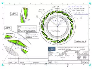
Technical Status of the Project • FE-I4 – New pixel front-end chip for IBL • 20 x 19 mm2 real-estate, more that 70 M-transistors, largest HEP chip ever. • 2 year design work for a team of ~15 engineers + several physicists from 5 laboratories. • Three design reviews: 17/3/2008, 3-4/11/2009, 16/4/2010 - submission to IBM: 17/5/2010 • Sensor prototypes for FE-I4 under processing – 3 technologies considered: Planar Sensors, 3D Sensors, Diamonds. • Expected sensors bump-bonded to FE-I4 for next fall • IBL Layout finalised – 14 staves with 32 FE-I4 chip modules at R=3.2 cm • Stave baseline (following last December review’s recommendations) • Low density carbon foam (ρ = 0.2 g/cm3), thin wall titanium cooling pipe (d=2mm), CO2 cooling. • Fitting and permanent cooling joints under prototyping. • FEA analysis on going, thermal figure of merit measurement on samples • Mechanical design of the whole IBL detector • 3D model and FEA for the whole detector on going. • Installation mock-up under construction in bld.180 at CERN. • Internal electrical services, flex hybrid in prototype phase. • New ROD/BOC (off-detector readout). • Modernized version of the Pixel VME ROD – more compact (x4 more channels/board) increased performance, large reduction of component count with state of the art FPGA technology. More info at this AUW: see IBL session and Maurice (FE-I4) and Tobias (BOC/ROD) talks in the Electronic sessions.
TDR, Schedule • IBL TDR • Planned for beginning of April - ~2 month delay • Technical part in good shape • Motivation of the project need to be strengthened • “Insurance policy” for existing B-layer failures • Improve physics performance of existing tracker – critical manpower for simulation (IBL geometry, 2, 3 x 1034 luminosity, inefficiency of Pixel/SCT) – Have limited demonstration for TDR(~1÷2 moths), in medium longer time add stronger/refined physic cases to defend in front of FA (time scale from iMoU to final MoU, ~1 year). • Radiation damage of existing BL (one of the main reasons for the design two years ago – is a weaker motivation today) – we want to keep design specification of IBL for 1x10¹⁵ n/cm2 (smaller R, unknown when IBL will be replaced by a new ID). • IBL schedule – plan to be ready for installation for end of 2014 • It cannot be ready before • Need to develop critical technology prototypes (FE-I4, sensors, light support structure, develop and make safe proof beam-pipe extraction/IBL insertion) • Backup policy in case the Pixel system develops serious problems – if ready and is not needed can wait for shut down (we do not ask today machine to schedule a shutdown); • Need a a long shutdown window (8 ÷ 9 months) for installation (synchronize with LHC machine installation plans); • We may want to accumulate some integrate luminosity in ATLAS before touching the ID tracker system. Need to understand how machine luminosity plans will develop.
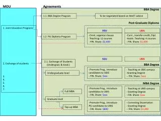
Memorandum of Understanding 1/2 • Why going to a Memorandum of Understanding: • Agree on a common target project time scale – define envelope cost • Define work sharing – cost sharing – deliverable responsibilities • Put together a collaboration fully capable to construct the detector – this is much more than a collection of R&D projects! • Keep a sense of overall project and team spirit – keep momentum high • IBL (interim)-MoU Status – Steps toward project shaping: • “IBL Kick-off” meeting (8/7/2009) • Institutes express their interest in the IBL based on project WBS (Workpackage Breakdown Structure). • Extended Pixel IB (1/03/2010) • Annexes of the iMoU presented and discussed with Institute representatives. • NCP Meetings (25/02/2010 and 22/04/2010). • Feedback from Funding Agencies on funding and general project support • Who has to sign the iMoU.
Memorandum of Understanding 2/2 • IBL Memorandum of Understanding (MoU) • BetweenThe ATLAS COLLABORATION, andFunding Agencies/Institutions of the ATLAS Collaboration constructing the IBL (for the ATLAS construction was between Institutes and CERN). • The MoU comprises all of the actions needed to construct and commission the IBL. The operation and maintenance of IBL is not a part of the present MoU and will be included, following its completion, within the M&O MoU framework. (IBL once delivered will be part of the Pixel Detector) • Annexes define: work sharing and responsibility, cost contribution, project organization and management structure. • IBL interim MoU – Why an interim MoU? • Ad Interim MoU until sensor technology is chosen (Planar Silicon / 3D Silicon / Diamond) - Decision on sensor technology (early 2011) – Sensor R&D and IBL communities work in tight collaboration to finalise a design matching IBL specification. • Consolidate interest of Institutes and availability of funds • Financing the project • Follow “CORE” costing. These costs do not include contingency (and manpower too). • Project funded through M&O-B, fresh Project money, M&O-A. • Strongly based on deliverables
Institutes and Contributions to IBL (Draft) Technology options refer to supplementary costs that are sensor technology specific and will be known before the definite MoU takes effect. So far, France, Italy and US have requested their shares to be moved from M&O to Project part. Note: the numbers in the table "are not final, nor are the suggested financial contributions yet firm, but are meant for a common overall discussion.”
Annex 5: IBL Payment Profile • Funding profile follows schedule for “ready to installation in 2014” • 2010 Large fraction for prototyping (FE-I4, sensors, modules, staves,…)
IBL Organization (Annex 2) • Annex 2 describes IBL organization and operation of its control structures • IBL MB (Management Board) and IB (Extended Pixel Institute Board) • The IBL MB controls the execution of the project. • The IB is an extension of the Pixel IB • Working Groups • The construction activities of the whole IBL project are divided into four working groups. • Two cordinators for each working group with defined mandate.
Conclusion • Very good technical progresses on the whole project • FE-I4 submission scheduled for May 17th. • Money for submission is being collected per IBL iMOU sharing. • TDR well on its way (200 pg) • Need simulation effort (and manpower) for stronger Physics justification • MoU (ad interim form) in its final discussion phase • Ready to start collecting signatures
Annex 4: Tentative Contribution to IBL Technology options refer to supplementary costs that are sensor technology specific and will be known before the definite MoU takes effect. So far, France, Italy and US have requested their shares to be moved from M&O to Project part. Note: the numbers in the table "are not final, nor are the suggested financial contributions yet firm, but are meant for a common overall discussion.”