Download
1 / 21
250 likes | 558 Views
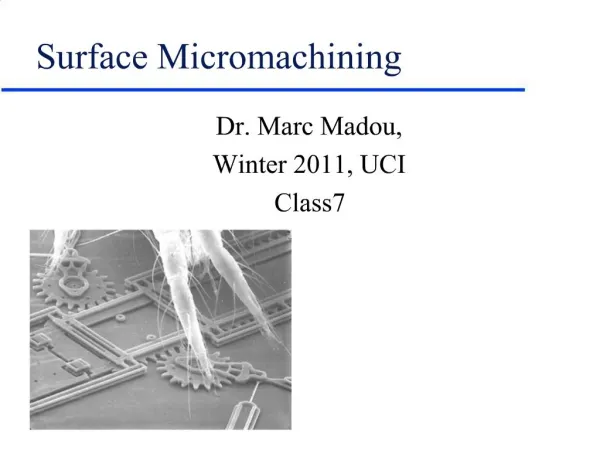
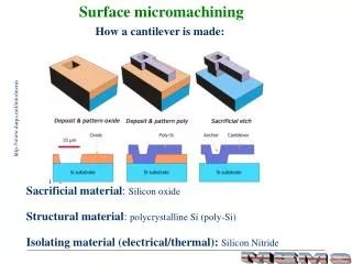
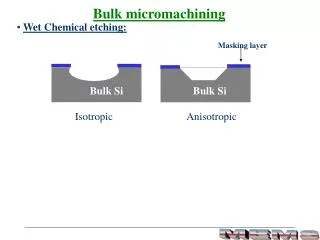
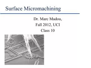
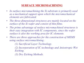
Lecture 16 - Surface Micromachining. Bulk Micromachining: Three dimensional features are etched into the bulk of crystalline or noncrystalline materials Surface Micromachining:

E N D
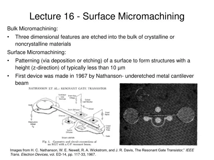
Lecture 16 - Surface Micromachining Bulk Micromachining: • Three dimensional features are etched into the bulk of crystalline or noncrystalline materials Surface Micromachining: • Patterning (via deposition or etching) of a surface to form structures with a height (z-direction) of typically less than 10 µm • First device was made in 1967 by Nathanson- underetched metal cantilever beam Images from H. C. Nathanson, W. E. Newell, R. A. Wickstrom, and J. R. Davis, The Resonant Gate Transistor,” IEEE Trans. Electron Devices, vol. ED-14, pp. 117-33, 1967.
Notable Devices First Si Device: • Howe and Muller made free standing polysilicon beams formed by underetching SiO2 in 1982 with a device used as a resonator to measure mass -chemical adsorption on the beam (conventional surface micromachining) Movable mechanical device: • Gabriel et all, made movable mechanical pin joints, springs, gears, cranks, sliders, etc in 1988. First commercial product: • Analog Devices made the first commercially successful product with their ADXL-50 accelerometer for activating air bag deployment in 1991 Images from Goodenough, F. “Airbags Boom When IC Accelerometer Sees 50 G.” Electronic Design. August 8, 1991.
Hinged Poly-Silicon Structures can be made horizontally and erected via the poly-Si hinge How would you make this?
Integrated Optics with Hinges Micromachined integrated optics for free space interconnections, Pister et al., UCB
Other Hinged Structures A microrobot is envisioned using Pi hinges and polysilicon plates. Electrostatic forces are used to actuate the “wings”. From K. Suzuki et al., JMEMS, 3, 4-9, 1994. Iwase and Shimoyama, JMEMS, 14, 6, 2005.
Surface Micromachining Surface Micromachining: • Is the addition and subtraction of materials on (and sometimes within) silicon wafers • Key distinguishing feature of MEMS/NEMS surface machining is the presence and removal of sacrificial layers, to release structures so that they are free to move. * *Sandia National Laboratories http://mems.sandia.gov/scripts/index.asp *
How can we make this? Sacrificial Materials Most popular sacrificial layer: Additional options: • Wet oxides and high-pressure oxides (HiPOx) for thick sacrificial layers • PECVD oxide and nitride (etched by HF if hydrogen incorporation is high) • Metals • Al using virtually any acid etch • Cu using acids mixed with H2O2 or Cu etchants such as Cu2SO4 • Au using an Au specific etchant of KI3 • Dendritic polymers that thermally decompose to a gas above a certain temperature
Single Beam Release Process 1) 2) 3) 4) 5)
LM + 2tPSG Process Details 1. PSG CVD deposition: sample at 400ºC inside a plasma chamber (pressure @ 2 Torr, with flow ratios for PH3 : SiH4 : N2 : N2O of [1 : 20 : 80 : 220]). Deposition rates can vary between 0.01 to 0.5 µm/min depending on plasma power and gas flow rates. Etching PSG is a wet process, not dry, intended to form “sloping” edges not a sharp edge.
Process Details cont. 3. Poly-Si is not a line-of-sight deposition (unlike e-beam or thermal evaporation dep.), rather CVD or high-pressure short-distance sputtering is used for best step coverage. CVD of poly-Si is typically at 600 ºC using SiH4 gas followed by annealing at 1000ºC. Dopants can be added to make the poly-Si n-type or p-type. During anneal, poly-Si next to PSG generally gets doped n-type (not p-type). 4. Etching of the poly-Si can be dry (e.g. SF6 plasma) or wet (e.g. KOH). Dry etching will etch into the PSG sacrificial layer, vs. wet will stop on the PSG layer (etch stop layer). Dry etching can use PR as an etch mask, vs wet will require PSG, Si3N4, or other etch mask. Wet etch ratio for Si vs PSG using KOH is about 1000 to 1. Etch ratio for Si vs Si3N4 is >10,000 to 1. 5. The etch rate increases for PSG for increased dopant concentration. Thicker layers etch faster than thinner layers (i.e. ). Etch undercut rate typically is ~1µm/min for layers thicker than 0.1 µm. Si3N4 is the most common material used to protect layers during sacrificial layer etching.
Sacrificial Layer Etching Improvements • HF:H2O (1:1) historically used, • But HF:HCl (1:1) etches PSG oxide layers twice as faster and nitride isolation layers half as fast (i.e. removes the oxide layer, leaves the nitride layer). • PSG historically used, • But BPSG (borophosphosilicate glass) can be etched 4 times faster using HF:HCl.
Stiction Definition: literally is static friction: the adhering of thin micromachined layers to a substrate. This is a major problem with MEMS devices. • Sacrificial layer etching is a wet process, thus it creates “activated” surface sites • During drying and due to capillary forces, layers can re-attach to the substrate through Van der Walls or hydrogen bonding (debatable as to which one) Water has a high surface tension, and as it dries, capillary forces pull structures together. Once stiction occurs, the force needed to free the structure typically destroys it.
Methods to Limit Stiction Problems • Incorporate to limit the area where stiction can occur • Complicated, additional mask and processing steps • Incorporate a material between layers that can be removed later by an O2 plasma • Some fluorocarbon polymers can be left in place because they “lubricate” a structure’s motion • Problem: polymers are not always compatible with high temp processing • Incorporate to hold structure in place that can later be vaporized using high current pulses • Contamination problems due to vaporization • Super critical CO2 drying
Super Critical CO2 Drying If water had no surface tension, then structures wouldn’t be pulled together due to capillary forces. Supercritical CO2 has extremely low . Method: • Water is displaced with methanol or IPA • Methanol or IPA is displaced with liquid CO2 inside a pressure chamber • The pressure chamber is heated past the supercritical point Supercritical point is the Pressure / Temperature point above which a supercritical liquid exists which is neither a liquid nor a gas. It has gas-like characteristics of low viscosity and liquid-like characteristics of high density. It also has extremely low surface tension. Supercritical point for water is 374ºC and 218 atm. Supercritical point for CO2 is 31.2ºC and 72.8 atm. Watch the youtube video of a Super Critical Liquids: http://www.youtube.com/watch?v=yBRdBrnIlTQ&feature=related Watch the youtube video of a Tousimis Super Critical Dryer in action http://www.youtube.com/watch?v=B_YEbjmGcmU http://www.youtube.com/watch?v=Q6Qkl40lsww
Hinged Poly-Si 7) PSG etch
Polyimide Hinge Process 7) PSG Etch
Quotes: • First keep the peace within yourself, then you can also bring peace to others. - Thomas Kempis • Have patience with all things, but first of all with yourself. - St. Francis de Sales • A person with outward courage dares to die. A person with inward courage dares to live. - Lao-Tzu • Forgiveness means giving up all hope of a better past. - Landrum Bolling