Download
1 / 46
720 likes | 1.39k Views
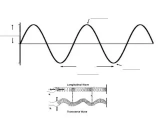
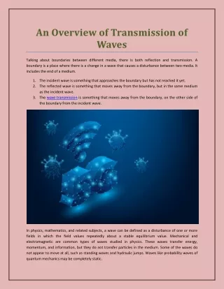
Reflection and Transmission of Waves. 4.5.1 Describe the reflection and transmission of waves at a boundary between two media. This should include the sketching of incident, reflected and transmitted waves.

E N D
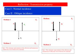
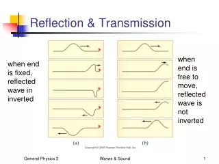
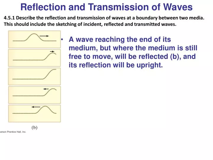
Reflection and Transmission of Waves 4.5.1 Describe the reflection and transmission of waves at a boundary between two media. This should include the sketching of incident, reflected and transmitted waves. • A wave reaching the end of its medium, but where the medium is still free to move, will be reflected (b), and its reflection will be upright.
Reflection and Transmission of Waves 4.5.1 Describe the reflection and transmission of waves at a boundary between two media. This should include the sketching of incident, reflected and transmitted waves. • A wave hitting an obstacle (fixed end) will be reflected (a), and its reflection will be inverted. It has undergone a 180o phase change or change in phase.
This is because the instant the pulse hits the fixed end, the rope attempts to move the fixed end upwards • It exerts an upwards force on the fixed end • By Newton’s third law, the wall will exert an equal but opposite force on the rope • This means that a disturbance will be created in the rope which, however is downwards and will start moving to the left
Reflection and Transmission of Waves • A wave encountering a denser medium will be partly reflected and partly transmitted; if the wave speed is less in the denser medium, the wavelength will be shorter.
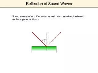
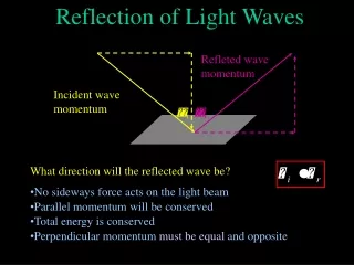
Reflection and Transmission of Waves • The law of reflection: the angle of incidence equals the angle of reflection.
Reflection • Visit this site for more in depth look at reflections. • http://physicsquest.homestead.com/quest11.html#anchor_38
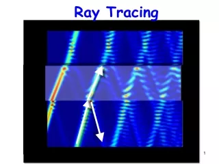
These following wavefronts can be used to show reflection (and refraction and diffraction and interference) of water waves
Normal Angle of reflection Angle of incidence =
The Law for Reflection • The angle of incidence is equal to the angle of reflection • Also - The incident ray, the reflected ray and the normal lie on the same plane • Use this rule for any ray or wave diagram involving reflection from any surface
For circular waves hitting a flat reflector, the reflected waves appear to come from a source, which is the same distance behind the reflector as the real source is in front of it • Also a line joining these 2 sources is perpendicular to the reflecting surface
I O
If a plane wave is incident on a circular reflector then the waves are reflected so that they • Converge on a focus if the surface is concave • Appear to come from a focus if the surface is convex
Echos • In the case of sound, a source of sound can be directed at a plane, solid surface and the reflected sound can be picked up by a microphone connected to an oscilloscope. • The microphone is moved until a position of maximum reading on the oscilloscope is achieved. • When the position is recorded it is found that again the angle of incidence equals the angle of reflection.
Refraction 4.5.2 State and apply Snell’s law. Students should be able to define refractive index in terms of the ratio of the speeds of the wave in the two media and also in terms of the angles of incidence and refraction. If the wave enters a medium where the wave speed is different, it will be refracted – its wave fronts and rays will change direction. We can calculate the angle of refraction, which depends on both wave speeds:
Refraction The law of refraction works both ways – a wave going from a slower medium to a faster one would follow the red line in the other direction.
Refraction • Why should a wave change direction when it changes media? • Think about a car driving from concrete onto sand. • Straight on • Concrete to sand at an angle • Sand to concrete at an angle
Refraction • As light travels from a less dense to a more dense medium, it is bent towards the normal. • As light travels from a more dense to a less dense medium it is bent away from the normal
Snell’s Law • State that the amount that a wave refracts as it travels between two media of different densities, can be expressed as a ratio of the speeds of the wave in the two media. • n1 = sinθ2 = v2 • n2 sinθ1v1 • n are the refractive indices • v is velocity of wave • θ1 = angle of incidence • θ2= angle of refraction
NOT GIVEN FORMULA!!!! • Where do you get your refractive index of a medium? • n = c / v • n is the refractive index • c is the speed of light in vacuum • v is the speed of light in medium
Refractive indices of common media ***in calculations, the refractive index of air is normally taken as 1.
Example Problem 1 • A ray of light is incident on the surface of the water in a pond with an angle of incidene of 35º. It bends, producing an angle of refraction of 25.5º. Calculate • a) the refractive index of the water • b) the speed of the light in the water • Answer: 1.33, 2.25 x 10⁸m/s
Example Problem 2 • A ray of light is incident on the surface of the water in a pond with an angle of incidene of 35º. It bends, producing an angle of refraction of 25.5º. Calculate • a) the refractive index of the water • b) the speed of the light in the water • Answer: 1.33, 2.25 x 10⁸m/s
Diffraction 4.5.3 Explain and discuss qualitatively the diffraction of waves at apertures and obstacles. The effect of wavelength compared to aperture or obstacle dimensions should be discussed. When waves encounter an obstacle, they bend around it, leaving a “shadow region.” This is called diffraction.
Diffraction • Consider every single point on the wavefront of the wave as itself a source of waves. In other words a point on the wavefront would emit a spherical wavelet or secondary wave, of same velocity and wavelength as the original wave. • Therefore as a wave goes through a gap or passed an obstacle the wavelets at the edges spread out. • This is a demonstration of Huygens’ principle. It can be used to predict the shapes of these wavefronts. • The new wavefront would then be the surface that is tangent to all the forward wavelets from each point on the old wavefront.
The amount of diffraction depends on the size of the obstacle compared to the wavelength. If the obstacle is much smaller than the wavelength, the wave is barely affected (a). If the object is comparable to, or larger than, the wavelength, diffraction is much more significant (b, c, d).
Diffraction 4.5.4 Describe examples of diffraction. • Diffraction occurs when the wavelength of the wave is long compared with the aperture. This explains why we cannot see around corners. The wave length of light is very short(about 6x10⁻⁷m). • This also explains why water waves and sound waves can be diffracted as their wavelengths are relatively long
Diffraction 4.5.4 Describe examples of diffraction. • Diffraction provides the reason why we can hear something even if we cannot see it. • An ordinary CD, when held at a sharp angle to a light source, will produce a spectrum characteristic of a reflection grating. The narrow, closely spaced grooves in the disc diffract the reflected light and produce the interference pattern that separates light into colors. • A simple transmission grating can be made by looking at the light from a showcase filament with your eyes nearly closed. Light passing through the narrow openings between your eyelashes will be diffracted and give rise to an interference pattern with its characteristic bright and dark bands.
Interference; Principle of Superposition • Superpositioin of waves occurs when two or more waves “superimpose” over one another to produce a new wave form which is a combination of the original ones. • Consider two waves one with frequency of 10Hz, the other with frequency of 12Hz. • Look at the new graph they make.
Interference; Principle of Superposition 4.5.5 State the principle of superposition and explain what is meant by constructive interference and by destructive interference. • Principle of super position – the resultant displacement at any point is the sum of the separate displacements due to the two waves.
Interference; Principle of Superposition 4.5.5 State the principle of superposition and explain what is meant by constructive interference and by destructive interference. • The superposition principle says that when two waves pass through the same point, the displacement is the arithmetic sum of the individual displacements. • In the figure below, (a) exhibits destructive interference and (b) exhibits constructive interference.
Interference; Principle of Superposition • Constructive interference takes place when the two waves are ‘in step’ with one another-they are said to be in phase. There is a zero phase difference between them. • Destructive interference takes place when the waves are exactly ‘out of step’-they are said to be out of phase. • There are several ways of saying this. One could say that the phase difference is equal to ‘half a cycle’ or ‘180 degrees’ or ‘π radians.’
Interference; Principle of Superposition • Constructive interference – mean the amplitudes add together • Destructive interference – means the amplitudes cancel each other out. • There are several ways of saying this. One could say that the phase difference is equal to ‘half a cycle’ or ‘180 degrees’ or ‘π radians.’
Interference; Principle of Superposition 4.5.7 Apply the principle of superposition to determine the resultant of two waves. These figures show the sum of two waves. In (a) they add constructively; in (b) they add destructively; and in (c) they add partially destructively.
For a more in depth look at superposition look at this activity. • http://physicsquest.homestead.com/quest11ac2.html
Young’s Double Slit Experiment • We can do this right now • http://www.studyphysics.ca/newnotes/20/unit04_light/chp1719_light/lesson58.htm
Double Slit Practice • A double slit consists of two slits, each of width 0.5cm that are 3.5cm apart, as shown below. A beam of sound, incident normally to the plane of the double slit, passes through the slits. A detector is moved along a line parallel to the plane of the double slit at a distance of 1.5m from the slits. The distance between points of maximum sound intensity is 1.2m. Determine the wavelength of the sound wave. • Answer 3.2x10⁻²m
Interference; Principle of Superposition 4.5.6 State and apply the conditions for constructive and for destructive interference in terms of path difference and phase difference. • Interference can take place if there are two possible routes for a ray to travel from source to observer. If the path difference between the two rays is a whole number of wavelengths, then constructive interference will take place. • Path difference=nλ (constructive) • Path difference=(n + ½ )λ (destructive) • For constructive or destructive interference to take place the sources of the waves must be phase linked or coherent.