Download

1 / 27
280 likes | 1.08k Views
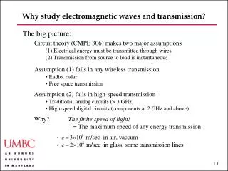
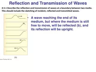
Electromagnetic waves: Reflection, Transmission and Interference. Monday October 28, 2002. Amplitude Transmission & Reflection. For normal incidence. Amplitude reflection. Amplitude transmission. Suppose these are plane waves. Intensity reflection. Amplitude reflection co-efficient.

E N D
Electromagnetic waves: Reflection, Transmission and Interference Monday October 28, 2002
Amplitude Transmission & Reflection For normal incidence Amplitude reflection Amplitude transmission Suppose these are plane waves
Intensity reflection Amplitude reflection co-efficient and intensity reflection
Intensity transmission Intensity transmission and in general R + T = 1 (conservation of energy)
Two-source interference What is the nature of the superposition of radiation from two coherent sources. The classic example of this phenomenon is Young’s Double Slit Experiment Plane wave () P S1 y x a S2 L
Young’s Double slit experiment Assumptions • Monochromatic, plane wave • Incident on slits (or pin hole), S1, S2 • separated by distance a (centre to centre) • Observed on screen L >> a (L- meters, a – mm) • Two sources (S1 and S2) are coherent and in phase (since same wave front produces both as all times) • Assume slits are very narrow (width b ~ ) • so radiation from each slit alone produces uniform illumination across the screen
Young’s double slit experiment • slits at x = 0 • The fields at S1 and S2 are Assume that the slits might have different width and therefore Eo1 Eo2
Young’s double slit experiment What are the corresponding E-fields at P? Since L >> a ( small) we can put r = |r1| = |r2| We can also put |k1| = |k2| = 2/ (monochromatic source)
Young’s Double slit experiment The total amplitude at P Intensity at P
Interference Effects • Are represented by the last two terms • If the fields are perpendicular • then, • and, In the absence of interference, the total intensity is a simple sum
Interference effects • Interference requires at least parallel components of E1P and E2P • We will assume the two sources are polarized parallel to one another (i.e.
Interference terms where,
Intensity – Young’s double slit diffraction Phase difference of beams occurs because of a path difference!
Young’s Double slit diffraction • I1P = intensity of source 1 (S1) alone • I2P = intensity of source 2 (S2) alone • Thus IP can be greater or less than I1+I2 depending on the values of 2 - 1 • In Young’s experiment r1 ~|| r2 ~|| k • Hence • Thus r2 – r1 = a sin r1 r2 a r2-r1
Intensity maxima and minima Maxima for, If I1P=I2P=Io Minima for, If I1P=I2P=Io
Fringe Visibility or Fringe Contrast To measure the contrast or visibility of these fringes, one may define a useful quantity, the fringe visibility:
Co-ordinates on screen • Use sin ≈ tan = y/L • Then • These results are seen in the following Interference pattern
Phasor Representation of wave addition • Phasor representation of a wave • E.g. E = Eosint is represented as a vector of magnitude Eo, making an angle =t with respect to the y-axis • Projection onto y-axis for sine and x-axis for cosine • Now write,
Phasors • Imagine disturbance given in the form =φ2-φ1 φ2 φ1 Carry out addition at t=0
Other forms of two-source interference Lloyd’s mirror screen S S’
Other forms of two source interference Fresnel Biprism S1 S s2 d s
Other sources of two source interference Altering path length for r2 r1 r2 n With dielectric – thickness d kr2 = kDd + ko(r2-d) = nkod+ ko(r2-d) = kor2 + ko(n-1)d Thus change in path length = k(n-1)d Equivalent to writing, 2 = 1 + ko(n-1)d Then = kr2 – kor1 = ko(r2-r1) + ko(n-1)d
Incidence at an angle Before slits Difference in path length a sin i i = a sin I in r1 After slits Difference in path length = a sin in r2 a sin Now k(r2-r1) = - k a sin + k a sin i Thus = ka (sin - sini)
Reflection from dielectric layer n1 n2 n1 • Assume phase of wave at O (x=0, t=0) is 0 • Amplitude reflection co-efficient • (n1n2) = 12 • (n2 n1) ’=21 • Amplitude transmission co-efficient • (n1n2) = 12 • (n2 n1) ’= 21 • Path O to O’ introduces a phase change A ’ A’ O’ ’ O t x = t x = 0
Reflection from a dielectric layer • At O: • Incident amplitude E = Eoe-iωt • Reflected amplitude ER = Eoe-iωt • At O’: • Reflected amplitude • Transmitted amplitude • At A: • Transmitted amplitude • Reflected amplitude
Reflection from a dielectric layer • At A’ A and ΔS1= z sin = 2t tan ’ sin z = 2t tan ’ Since, A’ The reflected intensities ~ 0.04Io and both beams (A,A’) will have almost the same intensity. Next beam, however, will have ~ ||3Eo which is very small Thus assume interference at , and need only consider the two beam problem.
Transmission through a dielectric layer • At O’: Amplitude ~ ’Eo ~ 0.96 Eo • At O”: Amplitude ~ ’(’)2Eo ~ 0.04 Eo • Thus amplitude at O” is very small O” O’