Download
1 / 47
580 likes | 890 Views
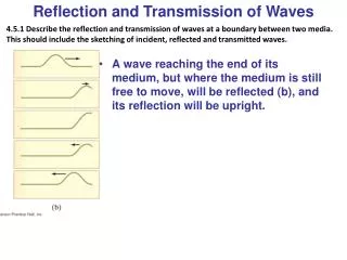
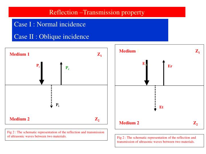
Medium 1. Medium 1. Z 1. Z 1. P i. E i i. P r. Er. Et. P t. Medium 2. Medium 2. Z 2. Z 2. Fig 2 : The schematic representation of the reflection and transmission of ultrasonic waves between two materials.

E N D
Medium 1 Medium 1 Z1 Z1 Pi Eii Pr Er Et Pt Medium 2 Medium 2 Z2 Z2 Fig 2 : The schematic representation of the reflection and transmission of ultrasonic waves between two materials. Fig 2 : The schematic representation of the reflection and transmission of ultrasonic waves between two materials. Reflection –Transmission property Case I : Normal incidence Case II : Oblique incidence
Derivation of reflection and transmitted coefficients Pi – Incident pressure : Pr – Reflected pressure Pt – Transmitted pressure . Similarly Ei,Er &Et are energies Z1, Z2 acoustic impedances of the mediums As the interface is stationary, the following assumptions can be made Pr + Pi = Pt ----- 1 Vi + Vr = Vt ------ 2 The acoustic impedance (Z) is given by P/V From eq. (1).Pr /Pi + 1 =Pt/Pi---- 3 R+1= T -- 5 From eq.(2) -Pr/Z1 + Pi/Z1= Pt/Z2 --- 4 -R+1 = T z1/z2-6 Defining reflection and pressure coefficients as R = Pr/Pi T = Pt/Pi 5+6: 2 = T + Tz1/z2 T= 2Z2 Z2+Z1 R= (Z2 - Z1) / (Z2+Z1)
Reflected and transmitted energy coefficients R ! = Er /Ei T ! = Et /Ei Hence, it can be observed that the reflection and transmission factors between two semi-infinite media (ie. not for layered structures) is only dependent upon the acoustic impedance and not parameters such as amplitude, frequency, etc E = P2/2Z R ! = Pr2/2Z1 Pi2/2Z1 = R2 =(Z2 - Z1)2/ (Z2+Z1)2 Unlike pressure , energy need be conserved R ! +T ! = 1 T ! = 4 Z1Z2 (Z2+Z1)2
Reflection Pressure coefficient = (Z2 - Z1) / (Z2+Z1) Transmission coefficient = 2Z2 / Z2+Z1 Reflection energy coefficient ==(Z2 - Z1)2/ (Z2+Z1)2 Transmission energy coefficient = 4 Z1Z2 / (Z2+Z1)2 Sum of pressure coefficients is not equal to 1 Sum of energy coefficients is equal to 1
Discussion (based on energy coefficients) Case 1 Z2 = Z1 In UT Which property is important T or R R = T = For transmitting from probe to Material T is important Two mediums & still having same acoustic impedance.Examples For defect detection R is important Case 2 Z2 >> Z1 R tends to T tends to Example/illustration Case III In between
Transmission from transducer/probe to material Case I : Transducer BaTio3 directly in contact with the material steel Interfaces are BaTio3, Air & Steel US generated at BaTio3 is transmitted to air and from air to steel BaTio3 to air - T12 Air to steel - T 23 BaTio3 to steel - T12 X T23 Works out to be 0.005%. Virtually no transmission T13 Case II – thin layer of couplant between Crystal and steel Same calculation as above. T works to be 16%, 3000 times higher Couplants need be used( water, oil, grease etc) Nature of couplant depends on surface roughness( ) Zc = sq.rt Z1x Z2 Couplant thickness wavelength in couplant /4
4. Precision Measurements of Density and Viscosity. Various applications in the manufacturing industry requires realtime, online measurement of material properties. Such applications include oil refineries, polymer industries, injection molding, glass melting, molten metal processes, etc. Using the longitudinal wave reflection factor between a solid and the fluid, techniques have been developed for the measurement of density of the fluid2. Similarly, the shear wave reflection factors have been employed for the measurement of viscosity of the melts2,3. [KB1] [KB1]I wonder how the detectability is an issue when we speak of reflection. Once, detectability is an issue, scattering and diffraction automatically comes into the picture. BEST TO AVOID CONTROVERSY.
App. Surface Roughness Amplitude RMS Microns Equivalent couplant viscosity 5 – 100 SAE 10 50 – 200 SAE 20 80 – 600 GLYCERIN 100 – 700 SAE 30 250 – 700 SAE 40 OVER 1000 CUP GREASE
Now reflection property- when it is important Flaw detection – a large acoustic impedance mismatch will result in larger reflection or better defect detection Flaw however large with same Z as the medium cannot be detected - why Reflection at flaws in test objects Reflection from air filled flaw – crack - -99.99% Water filled flaw - 93.7% Inclusions - 30 to 50 % Inclusions – why less – why a range of values
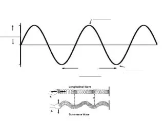
Reflection at oblique incidence-refraction-mode conversion Refraction Simple reflection and refraction When a wave encounters different medium where the wave speed is different, the wave will change directions. This bending of waves is refraction This refraction is upward or downward with respect original direction Depends on the --------- of the two mediums
Refraction and diffraction The direction of light propagation can be changed at the boundary of two media having different densities. This property- bending of light is called refraction, and is illustrated in the following figure for the boundary between air and water. • Away from the perpendicular if medium 2 is less dense than medium 1 • Toward the perpendicular if medium 2 is more dense than medium 1
Diffraction of sound waves is commonly observed; we notice sound diffracting around corners or through door openings, allowing us to hear others who are speaking to us from adjacent rooms. Many forest-dwelling birds take advantage of the diffractive ability of long-wavelength sound waves. Owls for instance are able to communicate across long distances due to the fact that their long-wavelength hoots are able to diffract around forest trees and carry farther than the short-wavelength tweets of song birds. Low-pitched (high wavelength) sounds always carry further than high pitched (low wavelength) sounds.
Relection-refraction and mode conversion Other than normal reflection and refraction, there are reflected shear and refracted shear waves (VS1 and VS2). This is due to mode conversion. At the interface, one mode is getting converted into the other mode. Longitudinal to shear: shear to longitudinal
Angular relationship between components- Snells law Convenient expression would be Very generalised- any component to any other component Snells law expressions- Normal refll. And Refr. Mode converted Refl. And Refr. Also between normal refraction and mode converted refraction
Mode conversion in UT= angle probe construction Lucite/perspex to steel–practical significance Two components in steel: two different flaws one in the path of longitudinal at a depth of 91mm and other in the path of transverse at a depth of 50mm : What is the CRT indication One large flaw having same depth in the path of long & shear – CRT indication
What is the way out- eliminate one – which one and how Increase of the incident angle- increase of refr.L and T At one angle the refr.L crazes the surface- moves along the surface-CRLW – I critical angle: Lucite steel ? Further increase II crtical angle – generation of surface waves–II critical angle for Lucite – steel Only one mode in steel- between I critical angle and II critical angle Calculate I and II critical angles for water and steel interface Second critical angle- what waves will be present at the interface
Construction of angle probe–range of angles Lucite block–cut a wedge–what is the wedge anglein relation to incident angle Why absorbent material – thick block on the right side
Can shear wave testing be carried out in immersion testing Yes and more elegantly – any angle between I & II by tilting the normal probe to the desired angle The angles marked in probe is normally for steel. For other materials, these angles are to be determined as these are needed in defect evalauation namely projected dstance and depth of the defect
Role of liquid couplant in angle beam testing- does the angle remains same or changed It can be mathematically established that the angle does not change because of intervening liquid couplant
No transmission- only reflection – relative intensities of longitudinal and transverse waves Interpretation of ultrasonic test results – 60 deg.Crack In a square block a large hole at the centre, the probe movement from the point above the centre will give four echos
Shear Horizontal (SH) and Shear Vertical (SV) waves Shear vertical – results from mode conversion of longitudinal waves- widely used in NDT- polarisedparallel to the of interface Shear Horizontal wave – polarised parallel to the plane surface of a specimen Calibrate the equipment to 182 mm of longitudinal waves using a normal probe and 91mm thick portion of IIW V1 block.= 100mm of shear wave calibration Angle probe is taken and kept at the centre of 100 mm arc,-the beam exit poit coinciding with the centre of the 100 mm arc. With Will the CRT show the reflection from 100 mm surface
Appearance initial pulse in the normal and angle beam techniques Why initial pulse is inside CRT in the angle beam calibration
References: 1. 2.I http://www.ndt.net/article/v05n09/berke/berke3.htm ndt-ed.org/.../CommunityCollege/Ultrasonics
Near and Far field effects Near zone–Fresnel zone– Zone immediately adjacent to the probe Far zone- Fraunhoffer zone- zone after the near field
1.Description and origin 2. Formula and variables affecting the zones 3. Influence on testing 4.Others Near Field Near field is characterised by nearly constant beam width and shape is same that of the circular crystal. The pressure or energy or internsity of US waves are nonuniformly varying having alternate maxima and minima. The crystal is having many microscrystals and emiitting waves.Due to interference, the energy is varying / The zone is also known as interference zone
Formula and variables affecting the near field N= D2/4λ--!!!! N = D2 f / 4 c Effective crystal size and frequency influence the near field As Dia of the crystal increases near field increases As frequency increases near field increases
Influence on testing Defect detection poses no problem as the width of the defect is very much larger than the width of the maxima and minima zones. Covered by both energies Sizing – not possible since DGS principle of sizing is based on uniform variation in sound pressure, energy or intensity Others 1. Near zone and dead zone Dead zone- immediately adjacent to the probe- extension of initial pulse caused by pulse duration etc. No detection, no thickness measurement Near zone only sizing not possible Others 2 -Defects in near zone – how to size Defect position cannot be changed- but defect can be made to be in the far zone - how
Near Field formula for angle probes Circular Transducer N = D2 / 4 λ - perspex depth x V(perspex_L)/V(Steel-T) Square Xal N = 1.3 L X w x 0.97 frequency / 4 shear wave velocity in Fe – perspex depth x V(perspex L) / V in steel (T) 1.3 conversion factor from circular to square 0.97 is the glueing factor – 97% is only active
Far field- Fraunhoffer zone – Divergence zone 1.Description andorigin 2. Formula and variables affecting the zones 4.Others 3. Influence on testing Far field Description and origin : after the last maxima – characterised by divergent beam – no interference after certain distance. Sound energy decreases uniformly Formula and variables influencing far field Sin ψ/2 = K λ/ D : K C/ D f – D and f influence in the same way. Higher D and f , lower the divergence: low D and f larger the divergence or beam spread
Influence on testing: detecting and sizing possible. This is because the sound pressure varies uniformaly Others: the K, constant has values 1.22, 1.08, 0.56 and 0.44 corresponding to intensities 0%, 10%,50% and 70%, with respect to axis taken to be 100% intensity Determines probeplacing intervals and speed of testing
Sensitivity of high frequency probes explained Which will have higher sensitivity and resolution and why
Width of the ultrasonic field at any distance from the probe for any intensity DGS principle is applicable only in the far field where sound energy varies uniformly Echo height or amplitude of the echo is dependant on D – inversely S – directly G - directly
Summary f & D N f & D ψ Penetrability and frequency Sensitivity and frequency
Attenuation of US waves Attenuation is the loss of ultrasonic wave energy as it propagates in a material. There are two main mechanisms of attenuation namely absorption and scattering in the MHz frequency range of UT. T = a + s where is the total attenuation coeff. a is the absorption att.coeff. s is the scattering att.coeff The absorption of US energy occurs mainly by the conversion of mechanical energy (sound) into heat. As the ultrasound propagates as a result of elastic motion within the material the alternate heating (during compression) and cooling (during rarefaction) of the material take place. (dislocation damping, internal friction
Scattering which is reflection in all directions occurs because most materials are inhomogenous. The inhomogeneities interact with propagating ultrasound leading to scattering. The inhomogeneities can be grain boundaries, minute gas pores, small size inclusions etc. It can be taken that the scattering takes place when the obstacle size 10 times or larger than the wavelength of ultrasound. This essentially means that when we have large grains scattering sets in or when the is very small compared to the grain size. Measurement of attenuation coeffiecient Measurement and comparison of echo heights More convenient way is to measure the echo height is by the dB- using the gain control knob.
Measurement of attenuation Attenuation equation I = I0 e - t where t is the thickness and I and I0 are the intensities. A convenient way of comparing the intensities is in terms decibels (dB) dB is one tenth of a bel What is bel : if p1 and p2 are acoustic powers, they are said to differ by n bels if p1/ p2 = 10 n n = log p1/ p2 dB = 10 log p1/ p2 Acoustic power is proportional to intensity. dB = 10 log I1/ I 2 but I is to Amplitude 2 dB = 10 log A12/ A22 or 20 log A1/ A2 It can be found out that if the second amplitude is half of the first amplitude, the change in dB will be 6 units. Similarly it can be worked out for other ratios. Measurement of attenuation db/mm
Origin of multiple echos, PRF, Pulse length l http://www.ndt.net/article/v05n09/berke/berke3.htm Nondestructive Material Testing with Ultrasonics - Introduction to the Basic Principles NDT.net - September 2000, Vol. 5
Why high frequency probes are more sensitive Limit of defect detctability - ?