Download
1 / 31
310 likes | 319 Views
TV Camera Tubes. Content: Types of TV camera Principle of video signal capturing Internal structure of TV camera Principle of solid state image scanner (CCD devices) CCD readout techniques. Types of TV camera. The first developed storage type of camera tube was Iconoscope Image-orthicon

E N D
TV Camera Tubes Content: Types of TV camera Principle of video signal capturing Internal structure of TV camera Principle of solid state image scanner (CCD devices) CCD readout techniques
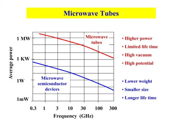
Types of TV camera • The first developed storage type of camera tube was Iconoscope • Image-orthicon • Vidicon • Plumbicon. • Solid state image scanner. • A TV camera tube may be called the eye of a TV system. A camera tube must have the following performance characteristics: • sensitivity to visible light, • wide dynamic range with respect to light intensity, and • ability to resolve details while viewing a multielement scene.
Optical to electrical conversion principle Photoelectric Effects The two photoelectric effects used for converting variations of light intensity into electrical variations are: (i) photoemission and (ii) photoconduction Photoemission: Certain metals emit electrons when light falls on their surface. Emitted electrons are called photoelectrons and the emitting surface a photocathode. The number of electrons which can overcome the potential barrier and get emitted, depends on the light intensity. Alkali metals are used as photocathode because they have very low work-function. Cesium-silver or bismuth-silver-cesium oxides are preferred as photoemissive surfaces because they are sensitive to incandescent light and have spectral response very close to the human eye. Photoconduction: The conductivity of the photosensitive surface varies in proportion to the intensity of light focused on it. In general the semiconductor metals including selnium, tellurium and lead with their oxides have this property known as photoconductivity. The variations in resistance at each point across the surface of the material is utilized to develop a varying signal by scanning it uniformly with an electron beam.
Picture Reception by photoemission process In tubes employing photoemissive target plates the electron beam deposits some charge on the target plate, which is proportional to the light intensity variations in the scene being televised. The beam motion is so controlled by electric and magnetic fields, that it is decelerated before it reaches the target and lands on it with almost zero velocity to avoid any secondary emission. On its return journey, it strikes an electrode which is located very close to the cathode from where it started. The number of electrons in the returning beam will thus vary in accordance with the charge deposited on the target plate. This in turn implies that the current which enters the collecting electrode varies in amplitude and represents brightness variations of the picture. This current is finally made to flow through a resistance and the varying voltage developed across this resistance constitutes the video signal.
Picture Reception by photoconduction process In camera tubes employing photoconductive cathodes the scanning electron beam causes a flow of current through the photoconductive material. The amplitude of this current varies in accordance with the resistance offered by the surface at different points. Since the conductivity of the material varies in accordance with the light falling on it, the magnitude of the current represents the brightness variations of the scene. This varying current completes its path under the influence of an applied dc voltage through a load resistance connected in series with path of the current. The instantaneous voltage developed across the load resistance is the video signal which, after due amplification and processing is amplitude modulated and transmitted.
Solid state image scanner History of Charged Couple Device (CCD)
Basic Operation of CCD Device The operation of solid state image scanners is based on the functioning of charge coupled devices (CCDs) which is a new concept in metal-oxide-semiconductor (MOS) circuitry. The CCD may be thought of to be a shift register formed by a string of very closely spaced MOS capacitors. It can store and transfer analog charge signals—either electrons or holes—that may be introduced electrically or optically.
Merits of CCD image sensor 1. Small in size and light in weight2. Low power consumption, low working voltage3. Stable performance and long operational life, resistant of impact and vibration4. High sensitivity, low noise and large dynamic range5. Quick respond, with self-scanning function, small image distortion 6. Applicable to ultra-large scale integrated circuit, with high integration of pixel, accurate size, and low cost
CCD readout techniques • Full frame and frame transfer devices tend to be used for scientific applications. • Interline transfer devices are used in consumer camcorders and TV systems. • Frame transfer imager consists of two almost identical arrays, one devoted toimage pixels and one for storage. • Interline transfer array consists of photodiodes separated by vertical transferregisters that are covered by an opaque metal shield
CCD readout technique Full Frame Transfer: Pixels accumulating light are organized into columns in area CCDs. Applying appropriate voltage to vertical electrodes shifts whole image (all pixels) along columns one row down. This means all image rows move to the next row, only the bottom-most row moves to so-called horizontal register. Horizontal register can be then shifted by horizontal electrodes to the output node pixel by pixel. Reading of array CCD means vertical shifts interlaced with horizontal register shifts and pixel digitization. Full frame devices expose all its area to light. It is necessary to use mechanical shutter to cover the chip from incoming light during readout process else the incoming light can smear the image. FF devices are best suited for astronomy tasks, because they use maximum area to collect light. Devices with really high QE are always FF devices. Kodak full frame CCDs
CCD readout technique • Frame Transfer (FT): FT devices comprise two areas, one exposed to light (Imaging Area—IA) and second covered by opaque coating (Storage Area—SA). When the exposition finishes, image is very quickly transferred from IA to SA. The SA then can be relatively slowly digitized without smearing the image by incoming light. This feature is sometimes called electronic shuttering. • Limitations: • Such kind of shuttering does not allow to expose dark frames. • Although the SA is shielded from the incoming light, charge can leak to SA from IA during slow digitization when imaging bright objects. • Important negative side of FT is its price.
CCD readout technique Interline Transfer (IT): IT devices work similarly to FT devices (they are also equipped with electronic shutter), but their storage area is interlaced with image area. Only odd columns accumulate light, even columns are covered by opaque shields. Odd columns are quickly transferred to even columns on the end of exposition, even columns are then shifted down to horizontal register and digitized. Progressive interline transfer Interlacing of image and storage columns limits the light-collecting area of the chip. This negative effect can be partially eliminated by advanced manufacturing technologies (like microlensing).
CCD readout technique Interlaced Readout: The television signal consists of interlacing images containing only half rows, so called half-frames. The odd half-frame contains rows 1, 3, 5 etc., the even half-frame contains rows 2, 4, 6, etc. Companies producing CCD sensors followed this convention and created CCD chips for usage in TV cameras, which also read only half-frames. But if only half of rows is read and the second half is dumped, the CCD sensitivity would decrease by 50%. This is why the classical “TV” CCD sensors electronically sums (see Pixel binning) neighboring rows so that the odd half-frame begins with single 1st row, followed by sum of 2nd and 3rd rows, then by sum of 4th and 5th rows etc. The even half-frame contains sum of 1st and 2nd row, followed by sum of 3rd a 4th rows etc. CCDs using this architecture are called interlaced read sensors, as opposite to sensors capable to read all pixels at once, called progressive read sensors. Despite the implementation of micro-lenses, the opaque columns reduces the quantum efficiency of IT CCDs compared to FF ones. Interlaced Interline Transfer sensor (even half-frame read)
How to obtain a color image? The colors red, green, and blue is used to create all the colors. This can be accomplished by grouping repeating patterns of two alternating cells. Each one of these cells has a one of three different color filters on it; either red, green, or blue. A diagram of a typical CCD pixel can be seen in figure 1 and a typical RGB CCD layout can be seen in figure 2. Figure 2: Diagram of a typical RGB pixel layout Figure 1: Cross-sectional view of a typical CCD cell (pixel)
How to obtain a color image? As can be seen from figure 2, the cells are situated in columns of alternating colors such that red, green, red, green is in one and blue, green, blue, green is in the one next to it before the column patters are repeated. Furthermore, the colors can be manipulated as much as is desired to make the colors appear correct, as once the CCD array is read by the hardware in the camera, software in the camera runs it through a set of algorithms in order to merge the intensity data from the CCD's pixels into color information that is then saved into a typical digital format, such as JPG or TIFF. Typically, one pixel in a JPG or TIFF file is comprised of four cells (one red, one blue, and two green) from a CCD array.
How to obtain a color image? A simplified example of how these colors are combined through their intensities and how the cells might charge up for one pixel in a JPG or TIFF file is as follows: First, let's say each cell can have an intensity value of 0 - 255 (8 bits). Also, one pixel, as previously stated, has one red, one blue, and two green cells. Now, let's take a 1 second exposure of a blue river. At the beginning of the exposure, each cell and sensor within it will start out with zero charge in its bucket. As time increases, however, they will begin to charge up to a maximum value (maximum intensity = 255 - if all cells have an intensity of 255, the color output is white, if all zero, the color output is black), however, they will charge up at different rates due to the filters (in this case, blue will charge faster than green or red). The charge versus time graphs for each color would look something like figure three below. So after one second, there is more blue than red or green. For instance, after one second, the red sensor detected an intensity of 50, the green of 80, and the blue of 150. Once the intensities of the charges are read off from the sensor, the intensity is then registered inside the software of the camera. These intensities are then merged together to form a single pixel.
Composite video signal • Composite means that the video signal includes several parts. • These parts are: • Camera signal corresponding to the desired picture information • Synchronizing pulses to synchronize the transmitter and receiver scanning • Blanking pulses to make the retrace invisible • These three components are added to produce the composite video signal.
Composite video signal Composite video signal for three consecutive horizontal lines
Horizontal and vertical blanking pulses in video signal 64 s 160 s The composite video signal contains blanking pulses to make the retrace lines invisible by raising the signal amplitude to black level during the time the scanning circuits produce retraces. All picture information is cut off during blanking time because of the black level. The retraces are normally produce within the time of blanking. The horizontal blanking pulses are included to blank out the retrace from right to left in each horizontal scanning line. The vertical blanking pulses have thefunction of blanking out the scanning lines produced when the electron beam retraces vertically from bottom to top in each field.