Download
1 / 47
480 likes | 716 Views
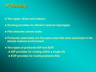
IP Routing. Two types: direct and indirect. Routing provides for efficient network topologies. Flat networks cannot scale. Protocols used today are the same ones that were used back in the shared network environment. Two types of protocols IGP and EGP.

E N D
IP Routing • Two types: direct and indirect. • Routing provides for efficient network topologies. • Flat networks cannot scale. • Protocols used today are the same ones that were used back in the shared network environment. • Two types of protocols IGP and EGP. • IGP provides for routing within a single AS • EGP provides for routing between ASs
Direct Routing Direct Routing • Network numbers must match for direct routing. • Different network numbers for indirect routing. • Remote nodes may use a combination of both direct and indirect routing. Direct Routing Station A 140.1.1.1 Station B 140.1.2.1 Station C 140.1.3.1 Indirect Routing Station D 140.2.1.1
Indirect Routing • Occurs when the source and destination network or subnet do not match. • Source will ARP for a router and send the datagram to the router. • The router will either forward the packet directly to the destination or it will forward it to another router in the path to the destination. • Routers decrement the TTL field. • Routers forward the packet based on the IP address and not the MAC address.
A Flowchart Packet Received NO YES If route is available, search for MAC address in ARP cache Received ARP Reply? Header and checksum valid? NO YES NO Send ICMP error message to originator NO Send ARP request and wait for a response Decrement TTL; TTL >= 0? MAC address found? YES YES Route Table lookup based on destination address Discard original packet Build new packet with MAC address and route packet through port found in routing table. Received ARP reply, insert MAC and IP address into ARP table NO NO Default route available? Route found? YES YES
Routing Protocols - Distance Vector 134.4.0.0 1 2 134.3.0.0 Network Metric Port Age 134.4.0.0 1 1 xxx 134.3.0.0 1 1 xxx 134.5.0.0 2 2 xxx 134.5.0.0
Updating Other Routers (Distance Vectors) • Upon initialization, each router reads its preconfigured IP address and metric (cost in hops) of all its active ports. • Each router transmits a portion of its routing table (network ID, metric) to each “neighbor” router. • Each router uses the most recent updates from each neighbor. • Each router uses the update information to calculate its own “shortest path” (distance in hops) to a network. • Tables are updated only: • If the received information indicates a shorter path to the destination network. • If the received update information indicates a network is no longer reachable. • If a new network is found.
W 1 X 1 Y 2 Z 3 A Bigger Update Router B Route Hop Route Hop Z 1 Y 1 X 1 Y 1 Z 2 Router A Z Y X Route Hop Route Hop Route Hop Network Hop Router Port Router C 1 Local 2 W X 1 Local 1 Y 2 B 1 Z 3 B 1 W
IP Routing Tables Port IP address (i.e., 132.2.2.2) 133.3.0.0 134.4.0.0 132.2.0.0 2.2 3.3 4.5 3.4 1.1 130.1.0.0 Routing Table Network Number Next Hop Hops Learned from Port 132.2.0.0 Direct 1 RIP 1 133.3.0.0 Direct 1 RIP 2 130.1.0.0 Direct 1 RIP 3 134.4.0.0 Direct 1 RIP 2
The Routing Information Protocol (Version 1) RIP Header RIP Data UDP Header UDP Data IP Header IP Data DA SA TF Data CRC
RIP Operational Types • RIP can operate in either ACTIVE or PASSIVE mode. • Active means that it builds routing tables and responds to RIP requests. • Passive means that it can build a routing table for its own use, but it does not respond to any RIP requests. • Most workstations (PCs) use a default gateway (i.e., router) and not a routing update protocol like RIP.
RIP Field Descriptions 0 31 Command Version Reserved Family of Net 1 Reserved Net 1 address Set to 0 Set to 0 Distance of network 1 Reserved Family of Net 2 Net 2 address Set to 0 Set to 0 Distance of network 2 Up to 25 entries DA SA TF IP Hdr UDP Hdr UDP Data CRC
Default Router and Gateways 130.1.1.1 Default Route 130.1.1.1 Default Route 0.0.0.0 129.1.1.2 129.1.1.1 Default Route 129.1.1.1 129.1.1.2
Disadvantages of the RIPv1 Protocol • RIPv1 only understands the shortest route to a destination, based on a simple count of router hops. • It depends on other routers for computed routing updates. • Routing tables can get large and these are broadcasted every 30 seconds. • Distances are based on hops, not real costs (such as the speed of a link). • Patched with split horizon, poison reverse, hold-down timers, triggered updates. • It continues to be a router-to-router configuration. One router is fully dependent on the next router to implement the same options. • Fix one problem and others appear.
Scaling with RIP Router B W 2 X 1 Y 1 Z 1 W 2 X 1 Y 1 Z 2 Z 1 Y 1 Router A X Z Y W 1 X 1 Y 2 Z 3 Router C • Router A previously sent its table W 1 X 1 Y 2 Z 3 W
Routers and Subnet Masks 150.1.0.0 160.1.0.0 150.1.3.0 160.1.1.0 255.255.255.0 150.1.1.0 255.255.255.0 150.1.3.0 255.255.255.0
RIP Fixes • Split Horizon—Rule states that a router will not rebroadcast a learned route back over the interface from which the route was learned. • Hold-Down Timer—Rule states that when a router receives information about a network that is unreachable, the router must ignore all subsequent information about that network for a configurable amount of time. • Poisoned Reverse and triggered updates—Rule states a router is allowed to rebroadcast a learned route over the interface from which it learned it, but the metric is set to 16. A triggered update allows a router to broadcast its table when a network is found to be down.
Split Horizon Demonstrated Router B X 1 Y 1 Z 2 W 2 X 1 Y 1 W 2 Z 1 Y 1 Router A Z Y X W 1 X 1 Router C W 1 X 1 Y 2 Z 3 W
RIP Version 2 Command Version Unused Route Tag Address Family Identifier Net 1 address Subnet mask Next-Hop IP Address Metric Route Tag Address Family Identifier Net 2 address Subnet mask Next Hop Metric DA SA TF IP Hdr UDP Hdr UDP Data CRC
Authentication 31 0 Command Version Unused Authentification Type OxFFFF Password Password Password Password Address Family Identifier Route Tag Net 2 address Subnet mask Next Hop Metric
Subnet Mask Field 31 0 Command Version Unused Authentification Type OxFFFF Password Password Password Password Address Family Identifier Route Tag Net 2 address Subnet mask Next Hop Metric
Route Tag and Next-Hop Fields 31 0 Command Version Unused Authentification Type OxFFFF Password Password Password Password Address Family Identifier Route Tag Net 2 address Subnet mask Next Hop Metric
Multicast Support • RIPv2 uses the multicast address of 224.0.0.9 to multicast, does not broadcast its table. • MAC address of 01-00-5E-00-00-09. • Details of this conversion are covered in RFC 1700 and the multicast section of this book • RIPv1 uses a broadcast address in both the IP header and the MAC header. • IGMP is not used for this multicast support.
RIPv2 Compatibility with RIPv1 • Configuration parameters on the router for: • RIPv1 only – version 1 messages will be sent • RIPv1 compatibility – RIP 2 messages as broadcast • RIPv2 – Messages are multicast • None – No RIP messages are sent
Open Shortest Path First (OSPF, RFC 2178) • Shortest-path routes based on true metrics, not just a hop count. • Computes the routes only when triggered to or every 30 minutes (whichever is less). • Pairs a network address entry with a subnet mask. • Allows for routing across equal paths. • Supports ToS. • Permits the injection of external routes (other ASs). • Authenticates route exchanges. • Quick convergence. • Direct support for multicast in both the IP header and the MAC header.
An OSPF Network Other Autonomous Systems Backbone Area 0.0.0.0 Router Router Router Host Router PC Area 4 PC PC PC Area 1 Area 2 Area 5
OSPF Overview • Upon initialization, each router records information about all its interfaces. • Each router builds a packet known as the Link State Advertisement (LSA). • Contains a listing of all recently seen routers and their cost • LSAs are restricted to being forwarded only in the orginated area • Received LSAs are flooded to all other routers. • Each router makes a copy of the most recently “seen” LSA • Each router has complete knowledge of the topology of the area to which it belongs. • Adjacencies are formed between a Designated Router (and Backup DR) and other routers on a network. • Shortest Path Trees are constructed after routers exchange their databases. • Router algorithm only when changes occur (or every 30 minutes, whichever is shorter).
OSPF Media Support • Broadcast - Networks such as Ethernet, Token Ring, and FDDI. • Non-broadcast Multiaccess (NBMA) - access that does not support broadcast but allows for multiple station access such as ATM, Frame Relay, and X.25. • Point-to-Point - Links that only have two network attachments, such as two routers connected by a serial line.
Router Types Autonomous System Border Router Backbone Area 0.0.0.0 Internal Router Other Autonomous Systems Area BorderRouter Router Router Designated Router Backup DR Backbone Router Host Area 3 PC PC PC Area 4 Area 1 Area 2 Internal Router
Router Names and Routing Methods • Three types of routing in an OSPF network: • Intra-Area routing - Routing within a single area • Inter-Area routing - Routing within two areas of the same AS • Inter-AS routing Routing between AS systems
Message Types • OSPF routers communicate by sending Link State Advertisement (LSAs) to each other. • Type 1 - Router Links Advertisement • Type 2 - Network Links Advertisement • Type 3 - Summary Links Advertisement • Type 4 - AS Boundary Router Summary Link Advertisement • Type 5 - AS External Link Advertisement • Type 6 - Multicast Group Membership LSA • LSAs contain sequence numbers to detect old and duplicate LSAs.
Metrics (Cost) • Reference RFC 1253 • Metric = 10n8 / interface speed • Examples: • => 100 Mbps 1 • 10 Mbps 10 • E1 48 • T1 65 • 64 kbps 1562 • 19.2 kbps 5208 • 9.6 kbps 10416
Generic Packet Formula Version Type Packet Length Router ID Area ID Checksum Authentication Type Authentication LSA Specific1 – Hello, 2 – DB Description, 3 – LS Request, 4 – LS Update, 5 – LS Ack IP Header Protocol ID 89 IP Data CRC DA SA TF
The Hello Protocol C B 30 15 C B 89 A MC • Routers send periodic Hello messages to each other. • The packet contains: • The router’s selection of the DR and BDR • Router’s priority used to determine the DR and BDR • Configurable timers that include: • Hello Interval – To determine when you should hear from a neighbor • RouterDeadInterval – The period before a router is declared down • A list of neighbors the router has heard from • This can be turned off by setting the network to an NBMA. • This is useful when there is only one router on the cable segment A B D Designated Router Backup DR C
D-D Seq = x M, Master D-D Seq = y M, Master D-D Seq = y M, Slave D-D Seq = y+1 M, Master D-D Seq = y+1 M, Slave D-D Seq = y+n, Master D-D Seq = y+n, Slave LS Request LS Update LS Request LS Update LS Ack LS Ack Adjacency Router 2 Designated Router Router 1 Hello Down Down Hello DR = RT2 ExStart ExStart Exchange Exchange Loading Loading Full Full
Maintaining the Database • After Dykstra runs, the database is checked for consistency. • Uses the flooding procedure: • Receive an LSA • Check for the information in the database • Determine whether or not to forward this LSA to an adjacency • Reliability checked using an acknowledgment procedure. • Each LSA contains an age entry. • Sequence numbers are generated for every LSA.
OSPF Areas AS 1 ASBR Area 0 Could be a RIP network within the same domain as OSPF Backbone Router Backbone Router Backbone Router Internal Router Area 1 Area 2 Area Border Router
The Backbone Area • There must be at least one area in an OSPF network. • It is called the backbone area. • Designated by area ID of 0.0.0.0. • Primarily responsibility to propagate information between areas. • Has the same attributes as any other area. • Any network topology may make up the backbone. • It can be used as a real network with attachments.
The Area Border Router (ABR) • Connects an area (or areas) to the backbone. • Summarizes its area topology to the backbone. • Propagates summarized information from the backbone into its area. • Final router that receives an area’s LSA. • ABRs do not flood LSA information into the backbone • Only produces summaries to the backbone for the backbone to propagate to other areas • Uses the network summary LSA. • Summarized information is propagated in an area by the DR and its adjacencies.
Virtual Link Backbone Area Area 2.2.2.2 Area 1.1.1.1 ABR ABR Virtual Link
Inter-Area Routing AS 1 ASBR Area 0 Could be a RIP network within the same domain as OSPF Backbone Router Backbone Router Backbone Router Area 1 Area 2 Area Border Router
Information from other Autonomous Systems • Uses the ASBR. • Other ASs according to OSPF may simply be a RIP network within the same OSPF domain. • External LSA used. • Type 1 – The preferred route and used when considering the internal cost of the AS. • Type 2 – Advertising the same metric as was advertised by the ASBR. • These are used to calculate the shortest path to the ASBR.
Stub Areas Area 0 • An area that has only one entry and one exit point (must be the same area). • Used to reduce the number of external advertisements. • A stub area blocks AS external link advertisements. AS 2 Does not contain AS2 route entries Contains AS2 route entries Area 2 Area 1
RFCs Related to OSPF 2178 DS: J. Moy, “OSPF Version 2,” 07/22/97 (211 pages) (.txt format) (obsoletes RFC 1583). 2154 ES: M. Murphy, B. Badger, A. Wellington, “OSPF with Digital Signatures,” 06/16/97 (29 pages) (.txt format). 1850 DS: F. Baker, R. Coltun, “OSPF Version 2 Management Information Base,” 11/03/95. (80 pages) (.txt format) (Obsoletes RFC 1253). 1793 PS: J. Moy, “Extending OSPF to Support Demand Circuits,” 04/19/95 (31 pages) (.txt format). 1765 E: J. Moy, “OSPF Database Overflow,” 03/02/95 (9 pages) (.txt format). 1745 PS: K. Varadhan, S. Hares, Y. Rekhter, “BGP4/IDRP for IP—OSPF Interaction,” 12/27/94 (19 pages) .txt format). 1587 PS: R. Coltun, V. Fuller, “The OSPF NSSA Option,” 03/24/94 (17 pages) (.txt format). 1586 I: O. deSouza, M. Rodrigues, “Guidelines for Running OSPF Over Frame Relay Networks,” 03/24/94 (6 pages) (.txt format). 1585 I: J. Moy, “MOSPF: Analysis and Experience,” 03/24/94 (13 pages) (.txt format). 1584 PS: J. Moy, “Multicast Extensions to OSPF,” 03/24/94 (102 pages) (.txt, .ps formats). 1403 PS: K. Varadhan, “BGP OSPF Interaction,” 01/14/93 (17 pages) (.txt format) (obsoletes RFC 1364). 1370 PS: Internet Architecture Board, “Applicability Statement for OSPF,” 10/23/92 (2 pages) (.txt format).
Static versus Dynamic Routing • Entries in a routing table can be static (manually entered by the network administrator) or dynamic (learned through a routing protocol such as RIP). • Static entries: • In the workstation for either: • Default Gateway (router) - used by indirect routing • Place a static route in for one that is not learned through RIP, etc. • In the router: • Entered as 0.0.0.0 and the next hop (no subnet) to indicate a default route • Routers can broadcast this information to their networks to let everyone know which is the default router • A default router is one that all other look to for networks that are not in their tables • Static routes can be used to increase security on the network • Any IP network address can be manually entered into the routing table • The router administrator supplies: • IP Network address • Subnet mask • Next hop interface (the IP address of the next routers interface to get to the network)
Remote Networks Virginia T3 T3 T1 California Texas Z A T1 = 1.544Mbps T3 = 45Mbps
C D 0800 129.2.1.2 129.1.1.2 IP Data CRC Datagram Routing Host - 129.1.1.1 Host - 129.1.1.2 E D 129.1.1.3 C IP Header Router 129.2.1.1 B IP Header A 129.2.1.2 B A 0800 129.2.1.2 129.1.1.2 IP Data CRC PC DA SA TF Data CRC