Download
1 / 145
1.49k likes | 1.68k Views
IP Routing. Router. A Router is a physical device used to connect two different network (LAN), check their destination in Routing Table and transmit the message to the required LAN Work on logical address (IP) Maintain routing table Select best path Layer 3 device Connect different network

E N D
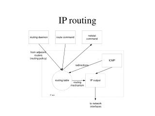
Router • A Router is a physical device used to connect two different network (LAN), check their destination in Routing Table and transmit the message to the required LAN • Work on logical address (IP) • Maintain routing table • Select best path • Layer 3 device • Connect different network • Backbone on internet • Packet filtering • Packet routing • It is denoted by symbol X
Interface • E0 – Ethernet • S0 – Serial Interface 0 • S1 – Serial Interface 1 DCE DTE DCE – DATA COMMUNICATION EQUIPMENT(CLOCK RATE) DTE – DATA TERMINAL EQUIPMENT
HOW TO LOGIN IN ROUTER Start Program Accessories Communication HyperTerminal
Router Modes • User exec mode:-> Router> • Privilege exec mode:-> Router# • Global Configuration Mode:-> Router(config)# • Other Configuration Mode:-> Router(config-if)# Router(config-line)# Router(config-router)# • Rx-boot Mode:-> It is used in password recovery. • Initial Configuration Mode:-> Setup mode
USER EXEC MODE • IT is represented by router>. • Minimal examination of the router. • No change will take place. router>enable router#
PRIVILAGE EXEC MODE • It is represented by router #. • Detail examination of the router & troubleshooting. router#config t {t=terminal} router(config)#
GLOBAL CONFIGURATION MODE • It is represented by router(config)#. • Configuration means router programming. • Change the router name router(config)#hostname GIT GIT(config)#
OTHER CONFIGURATION MODE • It is represented by router(config-if)# router(config-line)# router(config-router)# router(config)#interface ethernet 0 router(config-if)# router(config)#line console 0 router(config-line)# router(config)#router rip router(config-router)#
INDEX • Static Routing • Default Routing • Dynamic Routing • RIP • IGRP • EIGRP • OSPF
IP ROUTING • Static Routing • Static Routing occurs when you manually add routes in each routers routing table • Default Routing • We use default routing to send packets only one exit path out of the network • Dynamic routing • Dynamic routing is when protocols are used to find networks.
Static Routing GIT Family
STATIC ROUTE • A static route is a manually configured route on your router. Static routers are typically used in smaller network. • To configure a static route, use one of the two commands: Router(config)# Ip route Distination_networkSubnet_maskIp_address_of_next_neighbor Or Router(config)# Ip route Distination_networkSubnet_maskInterface_to_exit
20.0.0.1 Router-1 20.0.0.2 Router-2 X X S1 S0 E0 30.0.0.1 10.0.0.1 E0 30.0.0.2 10.0.0.2
Router-1 Enable Config t Hostname Router1 Int e0 ip address 10.0.0.1 255.0.0.0 no shut Int s0 ip address 20.0.0.1 255.0.0.0 no shut clock rate 64000 Exit Ip route 30.0.0.0 255.0.0.0 20.0.0.2
Router-2 Enable Config t Hostname Router2 Int e0 ip address 30.0.0.1 255.0.0.0 no shut Int s1 ip address 20.0.0.2 255.0.0.0 no shut Exit Ip route 10.0.0.0 255.0.0.0 20.0.0.1 Exit Show ip route
Configure Router 1 from PC1
Enable Config t Hostname rt1 Int e0 Ip address 10.0.0.1 255.0.0.0 No shut
int s0 ip address 20.0.0.1 255.0.0.0 no shut
int s0 clock rate 64000
exit exit show run
copy running-config startup-config (for saving configuration)
CONFIGURE ROUTER-2 AND PC2
enable config t hostname rt2 int e0 ip address 30.0.0.1 255.0.0.0 no shut
int s1 ip address 20.0.0.2 255.0.0.0 no shutdown
int s1 ip address 20.0.0.2 255.0.0.0 no shutdown exit ip route 10.0.0.0 255.0.0.0 20.0.0.2 exit
To check the connectivity from router ping 10.0.0.1 ping 10.0.0.2 ping 20.0.0.1 ping 20.0.0.2 ping 30.0.0.1
Default Routing • We use default routing to send packets only one exit path out of the network like Router-1 and Router-3. In Router-2 there are two exit path. IP ROUTE 0.0.0.0 0.0.0.0 20.0.0.1 Router-1 Router-2 Router-3 X X X
Routing Protocol • There are three types of routing protocol • Distance Vector • Link State • Hybrid
Routing Protocol • DistancevectorProtocol • Complete routing table send for route update • Exp – RIP, IGRP • Link State Protocol • Only change (through hello packet) send for route update • Exp - OSPF • HybridProtocol • Both feature Distance Vector & Link State • Exp - EIGRP
RIP ROUTING INFORMATION PROTOCOL
RIP • ROUTING INFORMATION PROTOCOL • Distance Vector Routing Protocol • Update Routing Table - Every 30 Sec. • Max Hop count - 15 • Class full
20.0.0.1 Router-1 20.0.0.2 Router-2 X X S1 S0 E0 30.0.0.1 10.0.0.1 E0 30.0.0.2 10.0.0.2
Set IP Address to PC1 • Winipcfg • IP Address – 10.0.0.2 • Subnet – 255.0.0.0 • Gateway – 10.0.0.1
Set IP Address to PC2 • Winipcfg • IP Address – 30.0.0.2 • Subnet – 255.0.0.0 • Gateway – 30.0.0.1
Router-1 Enable Config t Hostname Router1 Int e0 ip address 10.0.0.1 255.0.0.0 no shut Int s0 ip address 20.0.0.1 255.0.0.0 no shut clock rate 64000 Exit Router rip network 10.0.0.0 network 20.0.0.0
Router-2 Enable Config t Hostname Router2 Int e0 ip address 30.0.0.1 255.0.0.0 no shut Int s1 ip address 20.0.0.2 255.0.0.0 no shut Exit Router rip network 20.0.0.0 network 30.0.0.0
Router-1 Router-2 Router-3 20.0.0.1 20.0.0.2 40.0.0.2 40.0.0.1 X X X S1 S0 S0 S1 E0 E0 E0 30.0.0.1 50.0.0.1 10.0.0.1 30.0.0.2 10.0.0.2 50.0.0.2
Set IP Address to PC1 • Winipcfg • IP Address – 10.0.0.2 • Subnet – 255.0.0.0 • Gateway – 10.0.0.1
Set IP Address to PC2 • Winipcfg • IP Address – 30.0.0.2 • Subnet – 255.0.0.0 • Gateway – 30.0.0.1
Set IP Address to PC3 • Winipcfg • IP Address – 50.0.0.2 • Subnet – 255.0.0.0 • Gateway – 50.0.0.1