Download
1 / 16
170 likes | 305 Views
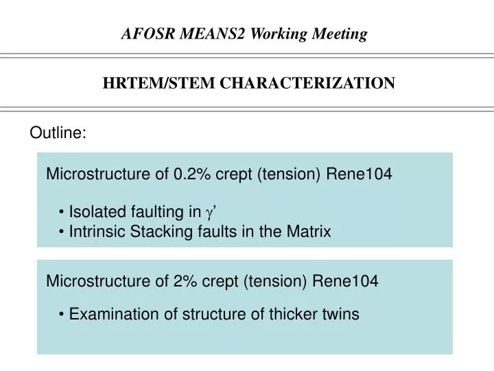
AFOSR MEANS2 Working Meeting. HRTEM/STEM CHARACTERIZATION. Outline:. Microstructure of 0.2% crept (tension) Rene104. Isolated faulting in ’ Intrinsic Stacking faults in the Matrix. Microstructure of 2% crept (tension) Rene104. Examination of structure of thicker twins.

E N D
AFOSR MEANS2 Working Meeting HRTEM/STEM CHARACTERIZATION Outline: Microstructure of 0.2% crept (tension) Rene104 • Isolated faulting in ’ • Intrinsic Stacking faults in the Matrix Microstructure of 2% crept (tension) Rene104 • Examination of structure of thicker twins
ISOLATED FAULTING • One of the feature of the 0.2% deformed microstructure • Not as prevalent as the SF on a different (111) slip plane • Faulting observed predominantly in the ’ precipitates OBSERVATIONS • Ended at the ’ interface • Ended at a SF • Transmitted through 100 nm
DETAIL OF THE ISOLATED FAULT ENDING AT THE ’ INTERFACE [110] A C B SESF C A C B A
THE INTERFACE DISLOCATION ANALYSIS Probe Deconvoluted Nye Tensor Moire Fringe Schematic Shear Strain MD Simulation Ni Ni3Al A A B zonalC
HOW DO ISOLATED FAULTS FORM? A 1) CSF Zonal partial= C A A SESF A A ISF ISF SESF 2) A ISF ?? SESF Zonal partial= C ESF A ESF ISF A ISF
ISOLATED FAULT ANALYSIS • Stronger intensity in the SESF (heavier elements => partitioning) • Stronger indication of Ordering • Confirmation of SESF or CSF not possible
ISOLATED FAULT ANALYSIS (-1-11) (111)
STACKING FAULT ANALYSIS IN THE MATRIX b=1/6 [112]@30° ISF b=-1/6 [112]@30° ISF
MICROTWIN STRUCTURE LAYER FAULTING AT THE INTERFACE Rene 104, 677ºC 690MPa 2.0% Strain 1/6<112> pairs 14 atomic planes 11 atomic planes
DFT comparison of MICRO-TWIN configurations • Super-cell configurations for Ni3Ti • True Twin (8 layers), Super-cell 16 layers(TTW_8_16) • Faulted True Twin (8 layers), Super-cell 16 layers(F_TTW_8_16) TTW_8_16 F_TTW_8_16 • Both super-cells were created from a perfect L12 NI3Ti by passing 1/3 [112]. (8 partials) Energy comparison (Super-cell energy 0K) TTW DO24 TTW_8_16 = -416.07eV F_TTW_8_16 = -416.22eV TTW TTW DE= -0.15eV/cell The DO24 fault translates into decreasing the energy by -96.5mJ/m2.
DFT calculation of MICRO-TWIN configurations • Super-cell configurations for Ni3Al • True Twin (8 layers), Super-cell 16 layers(TTW_8_16) • Faulted True Twin (8 layers), Super-cell 16 layers(F_TTW_8_16) TTW_8_16 F_TTW_8_16 • Both super-cells were created from a perfect NI3Al by passing 1/3 [112]. (8 partials) Energy comparison (Super-cell enthalpy) TTW DO24 TTW_8_16 = -349.19eV F_TTW_8_16 = -349.06eV TTW TTW DE= 0.13V/cell The DO24 fault translates into increasing the energy by 83.5mJ/m2.
DFT comparison of MICRO-TWIN configurations • Super-cell configurations for Ni3Al • True Twin (7 layers) with adjacent one layer pseudo-twin (TTW_Pa1_19) • True Twin (7 layers), with a fault and adjacent pseudo twin (TTW_Pn1_19) TTW_Pa1_19 TTW_Pn1_19 • Both super-cells were created from a perfect NI3Al by passing 7x 1/3 [112] and 1x 1/6 [112] (in case ofthe TTW_Pn1_19 one plane was skipped before passing the 1/6 [112] ). ? PTW Energy comparison (Super-cell energy 0K) TTW TTW TTW_Pa1_19 = -414.36eV TTW_Pn1_19 = = -414.28eV DE= 0.08V/cell The fault translates into increasing the energy by ~51.5mJ/m2.
DFT comparison of MICRO-TWIN configurations • Super-cell configurations for Ni3Ti • True Twin (7 layers) with adjacent one layer pseudo-twin (TTW_Pa1_19) • True Twin (7 layers), with a fault and adjacent pseudo twin (TTW_Pn1_19) TTW_Pa1_19 TTW_Pn1_19 • Both super-cells were created from a perfect L12 NI3Ti by passing 7x 1/3 [112] and 1x 1/6 [112] (in case ofthe TTW_Pn1_19 one plane was skipped before passing the 1/6 [112] ). ? PTW Energy comparison (Super-cell energy 0K) TTW TTW TTW_Pa1_19 = -492.76eV TTW_Pn1_19 = = -492.75eV Energetically the same!
EXTENDED FAULTS 2x 1/6[112]
OUTCOME AND FUTURE PLANS • ISOLATED FAULTING (UNDERSTANDING THE MECHANISM) => COMBINATION OF MICROSCOPY WORK AND PHASE FIELD) • STEM SEGREGATION STUDIES AND AB INITIO? • PAPERS • OBSERVATIONS OF ISOALTED FAULTING • MICROTWIN FAULTING AT THE INTERFACE AND COMPOSITIONAL EFFECTS