Download
1 / 46
460 likes | 543 Views
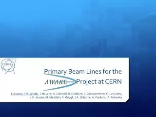
Primary Beam Lines for the Project at CERN. C.Bracco , G. Rumolo, F.M . Velotti J. Bauche , E. Gschwendtner, J. Hansen, L.K. Jensen, P. Muggli, A. Petrenko. Outlines. Reminder and updates: p + beam line e - beam line

E N D
Primary Beam Lines for the Project at CERN C.Bracco, G. Rumolo, F.M. Velotti J. Bauche , E. Gschwendtner, J. Hansen, L.K. Jensen, P. Muggli, A. Petrenko
Outlines • Reminder and updates: • p+ beam line • e- beam line • Common beam line: detailed overview on different options (side-injection and on-axis injection): • Requirements and constraints • Challenges and possible solutions • Summaryand conclusions
Proton Beam Line Plasma cell 1 s= 202 mm Laser Proton Not real bottleneck Laser, p+ beam line (20 m)
p+ & Laser beam Plasma cell Laser Proton BPM Not real bottleneck Mirror alignment wrt p+ beam: adjust p+ beam to reference trajectory mirror scan (losses) Possible interlocks: BPMs (2 needed) and BLM stop SPS extraction if beyond limits to avoid damaging mirror. BPM BLM
p+ & Laser beam Requirements: 0.1 mm & 0.02 mrad pointing precision for p+ beam at cell
Diagnostics 10 m BPG BPG BTV BPG BTV BPG 2.6 m 30 cm 38 mm Plasma cell 1 m drift with irises 1 m drift with irises e- Spectrometer • Plasma cell: 40 mm external Ø, 38 mm inner Ø (isolation, etc. 30 cm Ø) • 1 m drift (40 mm external Ø, 38 mm inner Ø) with irises up/downstream of plasma cell to intercept Rb • 2 BTVs (OTR screens) located ~1.5 m up/downstream of plasma cell profile and position measurements, used during setup to align p+ beam and laser (screens for laser and p+!). Spot size: 1sup=250 mm and 1sdown=0.8 mm • 3/4 BPGs (pickups) located at 1-6 m up/downstream of plasma cell define reference during setup and interlocked during operation (total accuracy ≤50 mm). Spot size: 1sup=500-230 mm and 1sdown=0.75-1.00 mm • To measure: current (intensity) + synchronization p+ and laser (< 100 ps)
Geometric constraints for e- beam RF gun Laser, p+ and e- beam line ~5 m 1.34 m 4.9 m p+ 20% slope Plasma cell 7% slope e- RF gun 20% slope RF gun
Electron beam line design Side & on-axis injection 22 main magnets Both injection schemes possible* s = 0.25 mm at merging point Focal point variable between plasma-cell entrance to 6 m using last 3 quadrupoles
Electron beam line design On-axis injection 17 main magnets s = 0.25 mm at merging point Focal point variable between plasma-cell entrance to 6 m using last 3 quadrupoles
Electron beam line design Side and on-axis injection design Pure on-axis injection design • Side and on-axis injection design: • both injection schemes possible • Very good control of dispersion functions • 30 % more magnets needed • Worst behaviour w.r.t. static errors • Pure on-axis injection: • Oscillating vertical dispersion function • Less magnets, hence more space for beam instrumentation • Better behaviour w.r.t. static errors
Proposed design for side-injection Any discontinuity in shielding e- from p+ disruptive two separate valves or pipe+ window for electrons
Proposed design for side-injection Any discontinuity in shielding e- from p+ disruptive two separate valves or pipe+ window for electrons
Side-Injection Experiment wish list: Vary merging point between 2 and 6 m from beginning of plasma cell Vary angle between 5 and 20 mrad e- 1.5 m 15 mm 1 mrad divergence from entrance of plasma cell induced by plasma on p+ beam p+
Side-Injection Experiment wish list: Vary merging point between 2 and 6 m from beginning of plasma cell Vary angle between 5 and 20 mrad e- 1.25 m 15 mm 1.5 m 1 mrad divergence from entrance of plasma cell induced by plasma on p+ beam p+ D2 movable D1 fixed 20 mrad merging point @ 1.25 m + 0.75 m = 2.0 m from beginning plasma cell
Side-Injection Experiment wish list: Vary merging point between 2 and 6 m from beginning of plasma cell Vary angle between 5 and 20 mrad e- 1.25 m 4.5 m e beam not shielded! 15 mm 1.5 m 1 mrad divergence from entrance of plasma cell induced by plasma on p+ beam p+ D2 movable D2 movable D1 fixed 20 mrad merging point @ 1.25 m + 0.75 m = 2.0 m from beginning plasma cell 3 mrad merging point @ 1.25 m + 5 m = 6.25 m from beginning plasma cell No screen over 4 m!!Region where e- approaching p+??
Side-Injection Experiment wish list: Vary merging point between 2 and 6 m from beginning of plasma cell Vary angle between 5 and 20 mrad e- 3.75 m 4 m 15 mm 1 mrad divergence from entrance of plasma cell induced by plasma on p+ beam p+ D2 movable D1 fixed D2 movable 20 mrad merging point @ 3.75 m + 0.75 m = 4.5 m from beginning plasma cell 6.5 mrad merging point @ 3.75 m + 2.3 m = 6.05 m from beginning plasma cell Need correctors around plasma (x-y steering)
Dipoles around Plasma cell • Dynamic range: • 5 - 30 Gauss Max field Bmax= 32 Gauss 15% - 85% Bmax • 100-640 A Max current Imax = 750 A 15% - 85% Imax Reasonably achievable dynamic range: 6.5 – 20 mrad 4.5 -6 m merging (could be < 4.5 but effect of missing screen to be evaluated) • Mechanical length of dipoles maybe too small longer magnets maximum kick <20 mrad(15 mrad) • Material in dipoles gap (plasma cell) any effect on magnetic field?
Vacuum chamber for side injection 1/2 e- e- p+ p+ e- • 1 mm thick walls, also in between the 2 beams (shield) • p+ beam offset by -6.5 mm • e- beam offset by 8.5 mm • 15 mm offset e-p beams p+
Vacuum chamber for side injection 1/2 e- e- p+ p+ • p+ beam: inner diameter 15 mm, outer 18 mm • E- beam: • Ellipse: • 32 mmx 21 mm inner • 34 mm x 23 mm outer e- p+
Magnets design for side-injection e- e- p+ p+ p+ losses! Magnets for e-beam (beam centred, mandatory for quadrupoles!): minimum aperture = 57 mm diameter + tolerance > 60 mm
Diagnostics 10 m BPG BPG BTV BPG BTV BPG 2.6 m e- 30 cm e- 38 mm Plasma cell 1 m drift with irises 1 m drift with irises 5 m e-/p+ common line e- Spectrometer p+ p+ • Shielding between e- and p+ beam: last BPG (active control on pointing precision) possible? Space for pickups? Not possible moving the BPG upstream in the non-common part loose accuracy on angle! e- e- p+ p+
Diagnostics See Patric’s talk! 10 m BPG BPG BTV BPG BTVs BPG 2.6 m 30 cm 38 mm Plasma cell 1 m drift with irises 1 m drift with irises 5 m e-/p+ common line e- Spectrometer • Shielding between e- and p+ beam: last BPG (active control on pointing precision) possible? Space for pickups? Not possible moving the BPG upstream in the non-common part loose accuracy on angle! • Conflict e-beam magnets (last dipole ~1m upstream cell) and BI ( possible move plasma cell and BI slightly downstream) • BTVs used also for e- beam line only during setup (additional screen or filters) 1 additional monitor downstream of plasma cell (position of spectrometer? Quadrupoles for e- after plasma needed?) 0.5-1m between the two BTVs. Spot size: 1sup=3.5 mm, 1sdown = 3 mm • Special design for diagnostics! (2 years from specs.) • Synchronization e-, p+ and laser
~5 m Effect of p+ beam on e- beam y e- 38 mm 15 mm p+ Dye z z’ Dyp s b Effect of p-beam on e-beam total wake field behind the source (slice l(z’)dz’ of protons) acting on the witness (electron bunch) per unit length of the pipe (W/m2) Charge density in p-beam slice dz’ @ z’ Kick induced on e-beam Ne = 1.2e9 electrons (longitudinal distribution in the e- bunch not taken into account as a first approximation) Total energy e-beam = 20 MeV
~5 m Effect of p+ beam on e- beam y e- 38 mm 15 mm p+ Dye z z’ Dyp s b Effect of p-beam on e-beam Only for small displacements (|Dyp| and |Dye|<< b) and if the source is highly relativistic (g>>1) Quadrupolar component (defocusing/focusing?) Dipolar component (kick) Here Dyp = - 6.5mm, Dye = 8.5mm, g = 480 and b = 19 mm So g>>1, but |Dyp| = 0.3 b and |Dye| = 0.4 b the linear expansion in dipolar and quadrupolarwakes is not applicable! Detailed studies are needed (existing model N. Mounet)
~5 m Effect of p+ beam on e- beam y e- 38 mm 15 mm p+ Dye z z’ Dyp s b Effect of p-beam on e-beam Total kick per unit length on the electrons from the part of proton bunch traveling in front of the electron bunch: Assuming that the kicks do not significantly change the electron beam trajectory along the common chamber*, we can calculate the total kick received by the electron beam as * It depends on the geometry (different aperture, irises, diagnostics, etc.)
Effect of p+ beam on e- beam y The wake is the integrated electromagnetic force, the wake per unit length is just the force x
Effect of p+ beam on e- beam y The wake is the integrated electromagnetic force, the wake per unit length is just the force x Second difference with the be = bp case: An additional term that needs to be evaluated with a large coefficient First difference with the be = bp case
Effect of p+ beam on e- beam y The wake is the integrated electromagnetic force, the wake per unit length is just the force x Second difference with the be = bp case: An additional term that needs to be evaluated with a large coefficient Not possible to infer the effect of p+ on e- beams analytically using other models as reference (i.e. SPS 26 GeV) tracking studies with detailed geometry need to be performed First difference with the be = bp case
On-axis Injection with shielding e- 20 mm p+ New design for vacuum chambers Magnets: >60 mm pole distance
On-axis Injection with shielding BPG BPG BTV e- 38 mm Plasma cell 1 m drift with irises 5 m e-/p+ common line 20 mm p+ New design for vacuum chambers Magnets: >60 mm pole distance Wakefield studies at merging!
~5 m Effect of p+ beam on e- beam for On-axis inj. y 38 mm e- 15 mm p+ z’ z s b |Dyp| and |Dye| = 0 Quadrupolar component (defocusing/focusing?) Dipolar component (kick) ~0 Bigger vacuum chamber, 58 mm inner Ø, over 4 m (last m 38 mm inner Ø)? x3.5 gain for resistive wall (1/b3)! Check effect of aperture variations induced wake fields (irises, diagnostics, etc.) Merging point between e- and p+ beam to be studied!
On-axis injection without shielding e- e- p+ p+ • 1 mm thick walls • 38 mm inner Ø, 40 mm outer Ø all along e- beam line • Alternative solution: • 58 mm inner Ø, 60 mm outer Ø over first 4 m (impact on magnet aperture > 60 mm )
Diagnostics See Patric’s talk! 10 m BPG BPG BTV BPG BTVs BPG 2.6 m 30 cm 38 mm Plasma cell 1 m drift with irises 1 m drift with irises 5 m e-/p+ common line e- Spectrometer • No conflict e-beam magnets (last dipole <1.5 m upstream cell) and BI • Conventional BPGs and BTVs mechanical design (60 mm Ø) • Need dedicated screens (hole for p+?) to steer and measure e- beam in presence of p+ beam (compensate for perturbations) during setup (laser?). Upstream Downstream e- e- p+ p+ 1sp=250 mm 1se=2.5 mm 1sp= 1 x 0.6 mm 1se= 2 x 6 mm
Diagnostics See Patric’s talk! 10 m BPG BPG BTV BPG BTVs BPG 2.6 m 30 cm 38 mm Plasma cell 1 m drift with irises 1 m drift with irises 5 m e-/p+ common line e- Spectrometer • No conflict e-beam magnets (last dipole <1.5 m upstream cell) and BI • Conventional BPGs and BTVs mechanical design (60 mm Ø) • Need dedicated screens (hole for p+?) to steer and measure e- beam in presence of p+ beam (compensate for perturbations) during setup (laser?). • No need for dipoles around plasma cell !! • Synchronization e-, p+ and laser • This diagnostics scheme (+1 additional BTV downstream of plasma cell) is compatible with on-axis injection with shielding between e- and p+.
Interface p+ and e- beam: summary 1/2 • Side-injection with shielding: • New design needed for vacuum chamber and diagnostics (to be confirmed if feasible, two years from specs for design, production and tests, cost!) • Conflict with last BPG for p+ beam (interlocked!) • Blind inside plasma cell, how can we measure Patric’s talk • Dipoles around plasma cell: large aperture (30 cm) and movable. What are the materials around the plasma cell? Requirements on magnetic field from experiment? Correctors for fine steering.
Interface p+ and e- beam: summary 2/2 • On-axis injection with shielding: • New design needed for vacuum chambers! • Do we need the shielding? • Detailed tracking studies with complete geometry (restrictions, irises, discontinuities, diagnostics) must be performed! • On-axis injection without shielding: • Standard design for vacuum chambers and beam diagnostics mechanics • New screens are needed to measure e- beam (profile and position) in presence of p+ to compensate for any effect (steering/focusing?) • Effect of p+ beam on e- from wake fields to be quantified (quadrupolar component) possible to further mitigate with larger aperture.
Conclusions • Proton beam: • Line and optics design are frozen (synchronization meas. still to be defined) • Requirements for beam diagnostics are defined including measurements for alignment of the mirror wrt p+ beam and laser and p+ beam all along plasma cell interlocks! • Electron beam • Many constraints! • Different flexible optics are defined: • Focal point from 0 to 6 m inside plasma cell • On-axis injection • Side-injection (convertible into on-axis injection with shielding) • New design for different components needed (depending on chosen option) • Suggestion: • On-axis injection until LS2 (impedance studies for side injection) • e- beam magnets design: 70 mm pole distance (to be confirmed by experts) ok for all options! • Vacuum chambers common part:58 mm inner Ø and 60 mm outer Ø over 4 m + 38 mm and 40 mm over last 1 m? Any issue with vacuum?
On-axis injection Preferred option! e- e- p+ p+ • 1 mm thick walls • 38 mm inner Ø, 40 mm outer Ø all along e- beam line • Alternative solution: • 58 mm inner Ø, 60 mm outer Ø over first 4 m (impact on magnet aperture > 60 mm )
On-axis Injection Backup option if clear indication of disruptive effects on e- beam! e- 20 mm p+ New design for vacuum chambers Magnets: >60 mm pole distance
Electron beam line design Side and on-axis injection design Pure on-axis injection design • Monte Carlo simulation to preliminary evaluate the effect of static errors in the line • Correction strategy: 1vs1 BPM – correctors • Correction method: SVD implemented in MAD-X • Only maximum beam envelope variation checked • Aim: 3s <= 20 mm
Side-injection no screen Reduce offset between p+ and e- beam Centre p+ beam in vacuum chamber reduce losses and resistive wall impedance (studies!) e- 7.5 mm Side-injection p+
Side-injection no screen Reduce offset between p+ and e- beam Centre p+ beam in vacuum chamber reduce losses and resistive wall impedance (studies!) Possibility of performing on-axis injection! (optics ready!) e- 7.5 mm Side-injection p+
Side-injection no screen Reduce offset between p+ and e- beam Centre p+ beam in vacuum chamber reduce losses and resistive wall impedance (studies!) Possibility of performing on-axis injection! (optics ready!) Possible use standard vacuum chambers Magnets for e-beam: minimum aperture 55 mm e- 7.5 mm Side-injection p+