Download
1 / 53
530 likes | 552 Views
Beam Transfer Lines. Distinctions between transfer lines and circular machines Linking machines together Blow-up from steering errors Correction of injection oscillations Blow-up from optics mismatch Optics measurement Blow-up from thin screens Verena Kain CERN

E N D
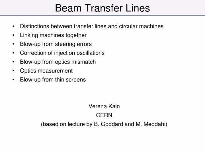
Beam Transfer Lines • Distinctions between transfer lines and circular machines • Linking machines together • Blow-up from steering errors • Correction of injection oscillations • Blow-up from optics mismatch • Optics measurement • Blow-up from thin screens Verena Kain CERN (based on lecture by B. Goddard and M. Meddahi)
Injection, extraction and transfer • An accelerator has limited dynamic range • Chain of stages needed to reach high energy • Periodic re-filling of storage rings, like LHC • External experiments, like CNGS CERN Complex Transfer lines transport the beam between accelerators, and onto targets, dumps, instruments etc. LHC: Large Hadron Collider SPS: Super Proton Synchrotron AD: Antiproton Decelerator ISOLDE: Isotope Separator Online Device PSB: Proton Synchrotron Booster PS: Proton Synchrotron LINAC: LINear Accelerator LEIR: Low Energy Ring CNGS: CERN Neutrino to Gran Sasso
Normalised phase space • Transform real transverse coordinates x, x’ by
Normalised phase space Real phase space Normalised phase space x’ x Area = pe Area = pe
General transport y s y s 2 x x 1 Beam transport: moving from s1 to s2 through n elements, each with transfer matrix Mi Twiss parameterisation
Circular Machine Circumference = L One turn • The solution is periodic • Periodicity condition for one turn (closed ring) imposes a1=a2, b1=b2, D1=D2 • This condition uniquely determines a(s), b(s), m(s), D(s) around the whole ring
Circular Machine • Periodicity of the structure leads to regular motion • Map single particle coordinates on each turn at any location • Describes an ellipse in phase space, defined by one set of a and b values Matched Ellipse (for this location) x’ x Area = pa
Circular Machine • For a location with matched ellipse (a, b), an injected beam of emittance e, characterised by a different ellipse (a*, b*) generates (via filamentation) a large ellipse with the original a, b, but larger e Turn 1 Turn 2 Turn 3 Turn n>>1 Matched ellipse determines beam shape
Transfer line One pass: • No periodic condition exists • The Twiss parameters are simply propagated from beginning to end of line • At any point in line, a(s) b(s) are functions of a1b1
Transfer line • On a single pass… • Map single particle coordinates at entrance and exit. • Infinite number of equally valid possible starting ellipses for single particle ……transported to infinite number of final ellipses… x’ x’ a1, b1 a2, b2 a*1, b*1 x x Transfer Line a*2, b*2 Exit Entry
Transfer Line • Initial a, b defined for transfer line by beam shape at entrance • Propagation of this beam ellipse depends on line elements • A transfer line optics is different for different input beams
Transfer Line • The optics functions in the line depend on the initial values • Same considerations are true for Dispersion function: • Dispersion in ring defined by periodic solution ring elements • Dispersion in line defined by initial D and D’ and line elements - Design bx functions in a transfer line - bx functions with different initial conditions
Transfer Line • Another difference….unlike a circular ring, a change of an element in a line affects only the downstream Twiss values (including dispersion) - Unperturbed bx functions in a transfer line - bx functions with modification of one quadrupole strength 10% change in this QF strength
Linking Machines • Beams have to be transported from extraction of one machine to injection of next machine • Trajectories must be matched, ideally in all 6 geometric degrees of freedom (x,y,z,q,f,y) • Other important constraints can include • Minimum bend radius, maximum quadrupole gradient, magnet aperture, cost, geology
Linking Machines Extraction Transfer a1x, b1x , a1y, b1y ax(s), bx(s), ay(s), by(s) s a2x, b2x , a2y, b2y Injection The Twiss parameters can be propagated when the transfer matrix M is known
Linking Machines • Linking the optics is a complicated process • Parameters at start of line have to be propagated to matched parameters at the end of the line • Need to “match” 8 variables (ax bx Dx D’x and ay by Dy D’y) • Maximum b and D values are imposed by magnet apertures • Other constraints can exist • phase conditions for collimators, • insertions for special equipment like stripping foils • Need to use a number of independently powered (“matching”) quadrupoles • Matching with computer codes and relying on mixture of theory, experience, intuition, trial and error, …
Linking Machines • For long transfer lines we can simplify the problem by designing the line in separate sections • Regular central section – e.g. FODO or doublet, with quads at regular spacing, (+ bending dipoles), with magnets powered in series • Initial and final matching sections – independently powered quadrupoles, with sometimes irregular spacing. Regular lattice (FODO) (elements all powered in series with same strengths) LHC SPS Final matching section Initial matching section SPS to LHC Transfer Line (3 km) Extraction point Injection point
Trajectory correction • Magnet misalignments, field and powering errors cause the trajectory to deviate from the design • Use small independently powered dipole magnets (correctors) to steer the beam • Measure the response using monitors (pick-ups) downstream of the corrector (p/2, 3p/2, …) • Horizontal and vertical elements are separated • H-correctors and pick-ups located at F-quadrupoles (large bx ) • V-correctors and pick-ups located at D-quadrupoles (large by) Pickup Corrector dipole Trajectory QF QF QD QD p/2
Trajectory correction • Global correction can be used which attempts to minimise the RMS offsets at the BPMs, using all or some of the available corrector magnets. • Steering in matching sections, extraction and injection region requires particular care • D and b functions can be large bigger beam size • Often very limited in aperture • Injection offsets can be detrimental for performance
Trajectory correction Uncorrected trajectory. y growing as a result of random errors in the line. The RMS at the BPMs is 3.4 mm, and ymax is 12.0mm Corrected trajectory. The RMS at the BPMs is 0.3mm and ymax is 1mm
Steering (dipole) errors • Precise delivery of the beam is important. • To avoid injection oscillations and emittance growth in rings • For stability on secondary particle production targets • Convenient to express injection error in s (includes x and x’ errors) Da [s] =((X2+X’2)/e) = ((gx2 + 2axx’+ bx’2)/e) Da Septum Bumper magnets kicker Mis-steered injected beam
Steering (dipole) errors • Static effects (e.g. from errors in alignment, field, calibration, …) are dealt with by trajectory correction (steering). • But there are also dynamic effects, from: • Power supply ripples • Temperature variations • Non-trapezoidal kicker waveforms • These dynamic effects produce a variable injection offset which can vary from batch to batch, or even within a batch. • An injection damper system is used to minimize effect on emittance LHC injected batch Beam 2 Injection osc. bunch number
Blow-up from steering error • Consider a collection of particles with max. amplitudes A • The beam can be injected with a error in angle and position. • For an injection error Day (in units of sigma = be) the mis-injected beam is offset in normalised phase space by L = Daye Matched particles Misinjected beam A L
Blow-up from steering error • The new particle coordinates in normalised phase space are Matched particles Misinjected beam • For a general particle distribution, where A denotes amplitude in normalised phase space A q L
Blow-up from steering error • So if we plug in the new coordinates…. 0 0 • Giving for the emittance increase
Blow-up from steering error A numerical example…. Consider an offset Da of 0.5 sigma for injected beam For nominal LHC beam: enorm = 3.5 mm allowed growth through LHC cycle ~ 10 % Misinjected beam e 0.5e Matched Beam
Injection oscillation correction • x, x’ and y, y’ at injection point need to be corrected. • Minimum diagnostics: 2 pickups per plane, 90° phase advance apart • Pickups need to be triggered to measure on the first turn • Correctors in the transfer lines are used to minimize offset at these pickups. • Best strategy: • Acquire many BPMs in circular machine (e.g. one octant/sextant of machine) • Combine acquisition of transfer line and of BPMs in circular machine • Transfer line: difference trajectory to reference • Circular machine: remove closed orbit from first turn trajectory pure injection oscillation • Correct combined trajectory with correctors in transfer line with typical correction algorithms. Use correctors of the line only.
Example: LHC injection of beam 1 Display from the LHC control room to correct injection oscillations closed orbit subtracted -6 to +6 mm Transfer line TI 2 ~3 km LHC arc 23 ~3 km Injection point in LHC IR2
Example: LHC injection of beam 1 • Oscillation down the line has developed in horizontal plane • Injection oscillation amplitude > 1.5 mm • Good working range of LHC transverse damper +/- 2 mm • Aperture margin for injection oscillation is 2 mm • correct trajectory in line before continue LHC filling
Blow-up from betatron mismatch • Optical errors occur in transfer line and ring, such that the beam can be injected with a mismatch. • Filamentation will produce an emittance increase. • In normalised phase space, consider the matched beam as a circle, and the mismatched beam as an ellipse. Mismatched beam Matched beam
Blow-up from betatron mismatch General betatron motion applying the normalising transformation for the matched beam an ellipse is obtained in normalised phase space characterised by gnew, bnew and anew, where
Blow-up from betatron mismatch From the general ellipse properties Mismatched beam where b a A giving Matched Beam generally
Blow-up from betatron mismatch We can evaluate the square of the distance of a particle from the origin as The new emittance is the average over all phases 0.5 0.5 If we’re feeling diligent, we can substitute back for l to give where subscript 1 refers to matched ellipse, 2 to mismatched ellipse.
Blow-up from betatron mismatch A numerical example….consider b = 3a for the mismatched ellipse Mismatched beam Then b=3a a Matched Beam
Dispersion measurement • Introduce ~ few permille momentum offset at extraction into transfer line • Measure position at different monitors for different momentum offset • Linear fit of position versus dp/p at each BPM/screens. • Dispersion at the BPMs/screens Position at a certain BPM versus momentum offset
Optics measurement with screens • A profile monitor is needed to measure the beam size • e.g. beam screen (luminescent) provides 2D density profile of the beam • Profile fit gives transverse beam sizes s. • In a ring, b is ‘known’ so e can be calculated from a single screen
Optics Measurement with 3 Screens • Assume 3 screens in a dispersion free region • Measurements of s1,s2,s3, plus the two transfer matrices M12 and M13 allows determination of e, a and b s1 s2 s3 s1 s2 s3
Optics Measurement with 3 Screens • Remember: ✕e Square of beam sizes as function of optical functions at first screen
Optics Measurement with 3 Screens • Define matrix N where S = NP • Measure beam sizes and want to calculate b1, a1, e • Solution to our problem S’ = N-1S • with b1g1-a12 = 1 get 3 equations for b1, a1 and e – the optical functions at the first screen with
…and if there is dispersion at the screens • Dispersion and momentum spread need to be measured independently at the different screens • Trajectory transforms with Ti transport matrix for d ≠ 0 • xi is the contribution to the dispersion between the first and the ith screen • Define 6 dimensional S and P and respective N and then same procedure as before
6 screens with dispersion • Can measure b, a, e, D, D’ and d with 6 screens without any other measurements. • Invert N, multiply with S to get S’
More than 6 screens… • Fit procedure… • Function to be minimized: Di…measurement error • Equation (*) can be solved analytically see • G. Arduini et al., “New methods to derive the optical and beam parameters in transport channels”, Nucl. Instrum. Methods Phys. Res., 2001. (*)
In Practice…. Difficulty in practice is fitting the beam size accurately!!!
Matching screen • 1 screen in the circular machine • Measure turn-by-turn profile after injection • Algorithm same as for several screens in transfer line • Only allowed with low intensity beam • Issue: radiation hard fast cameras Profiles at matching monitor after injection with steering error.
Blow-up from thin scatterer • Scattering elements are sometimes required in the beam • Thin beam screens (Al2O3,Ti) used to generate profiles. • Metal windows also used to separate vacuum of transfer lines from vacuum in circular machines. • Foils are used to strip electrons to change charge state • The emittance of the beam increases when it passes through, due to multiple Coulomb scattering. qs rms angle increase: bc = v/c, p = momentum, Zinc = particle charge /e, L = target length, Lrad = radiation length
Blow-up from thin scatterer Each particles gets a random angle change qs but there is no effect on the positions at the scatterer Ellipse after scattering After filamentation the particles have different amplitudes and the beam has a larger emittance Matched ellipse
Blow-up from thin scatterer Ellipse after filamentation uncorrelated 0 Matched ellipse Need to keep b small to minimise blow-up (small b means large spread in angles in beam distribution, so additional angle has small effect on distn.)
Blow-up from charge stripping foil • For LHC heavy ions, Pb53+ is stripped to Pb82+ at 4.25GeV/u using a 0.8mm thick Al foil, in the PS to SPS line • De is minimised with low-b insertion (bxy ~5 m) in the transfer line • Emittance increase expected is about 8%
Kick-response measurement • The observable during kick-response measurement are the elements of the response matrix R • ui is the position at the ith monitor • dj is the kick of the jth corrector • Cannot read off optics parameters directly • A fit varies certain parameters of a machine model to reproduce the measured data LOCO principle • The fit minimizes the quadratic norm of a difference vector V Reference: K. Fuchsberger, CERN-THESIS-2011-075 for mi>mj otherwise si… BPM rms noise Nc… number of correctors