Download
1 / 32
320 likes | 326 Views
Learn about the functions and applications of limiters, mixers, upconverters, and downconverters in bandpass circuits. Understand the operation and characteristics of these components for signal modulation and frequency conversion.

E N D
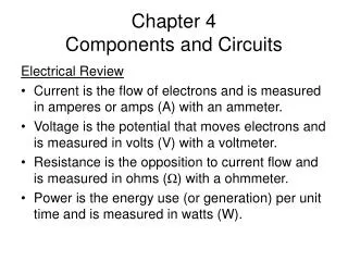
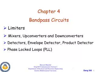
Huseyin Bilgekul Eeng360 Communication Systems I Department of Electrical and Electronic Engineering Eastern Mediterranean University Chapter 4 Bandpass Circuits • Limiters • Mixers, Upconverters and Downconverters • Detectors, Envelope Detector, Product Detector
Limiters • Limiter is a nonlinear circuit with an output saturation characteristic. • It rejects envelope variations but preserves the phase variations. Ideal limiter characteristic with illustrative input and unfilteredoutput waveforms.
Mixers are used in a variety of RF/microwave applications, including military radar, cellular base stations, and more. An RF mixer is a three-port passive or active device that can modulate or demodulate a signal. The purpose is to change the frequency of an electromagnetic signal while preserving phase and amplitude characteristics of the original signal Principal reason for frequency conversion is to allow amplification of the received signal at a frequency other than that of the RF. Figure 1: A mixer presented symbolically.
The three ports are referred to as the RF input port, LO (local oscillator) input port, and the IF (intermediate frequency) output port. A mixer is also known as a downconverter if the mixer is part of a receiver or as an upconverter if it is part of a transmitter. When the desired frequency is less than the second input frequency, the process is called down-conversion. The RF is then the input while the IF is the output. When the desired output frequency is greater than the second input frequency the process is called up-conversion. Here the IF is the input while the RF is the output.
In a receiver, when the LO frequency is less than the RF frequency, it is called low-side injection and the mixer is a low-side downconverter. When the LO frequency is above the RF, it is called high-side injection, and the mixer is a high-side downconverter.
Generally, a passive mixer is made of passive devices, such as diodes. An active mixer is made of active devices, such as transistors. Active or passive implementations are used depending on the application. Passive mixers are widely used due to their simplicity, wide bandwidth, and good intermodulation distortion (IMD) performance. Active mixers are mostly used for RFIC implementation. They are configured to provide conversion gain, good isolation between the signal ports, and require less power to drive the LO port. There are three basic types of active and passive mixers: unbalanced,single-balanced, and double-balanced.
Mixer parameters that engineers will find in a datasheet: • Conversion loss or gain: Measured in dB, conversion gain measures the signal gain in an active mixer, while conversion loss (known also as CL) measures the insertion loss in a passive mixer. Conversion gain is defined as the ratio of the IF output power to the RF input power. For passive mixers, CL is the most important parameter next to the noise figure. It is defined as the difference in power between the input RF power level and the desired output IF frequency power level. Of course, the lower the CL the better. Typical values of conversion loss range between 4.5 to 9 dB 2. Noise figure (NF): Defined as the added noise generated by the mixer and present at the IF output, the noise figure is the second important parameter (CL is the first) for the passive filter. For a passive mixer, the NF is almost equal to the loss. Mixer selection depends on many factors and, most of all, on the requirements of an application. Some applications require a specific amount of harmonic distortion. Finally, determine the type of packaging the mixer will have.
Mathematics of Mixers • Ideal mixer is a mathematical multiplier of two input signals. One of the signals is sinusoidal generated by a local oscillator. Mixing results in frequency translation. SSB mixer
Choosing LO Frequency of Mixers Up-conversion Down-conversion Bandpass Filter Baseband/bandpass Filter (fc-f0) • If (fc- f0)= 0 Low Pass Filter gives baseband spectrum • If (fc- f0 )> 0 Bandpass filter Modulation is preserved Filter Output: • If fc>f0 modulation on the mixer input is preserved ‘’ needs to be positive • If fc<f0 When complex envelope is conjugated ~sidebands are exchanged
- Amplitude is scaled by A0/2 i.e., f0>fc down conversion with high-side injection - Amplitude is scaled by A0/2 - Sidebands are reversed from those on the input Mixers (Up Converter and Down Converter) • Complex envelope of an Up Converter: • Complex envelope of a Down Converter: i.e., f0<fc down conversion with low-side injection - Amplitude is scaled by A0/2
In practice the multiplying operation needed for the mixer is realized by on of the • following: • A continuously variable transconductance device, i.e. Dual-gate FET • A non-linear device • A linear device with a time-varying discrete-gain. • Here we will look at 2nd approach.
Mixer Realization Without Multipliers • Multiplication operation needed by mixers can be obtained by using a nonlinear device together with a summer. Nonlinear device used as a mixer.
Frequency Multiplier • Frequency Multipliers consists of a nonlinear device together with a tuned circuit. • The frequency of the output is n times the frequency of the input.
Detector Circuits Signal processing Carrier circuits Transmission medium (Channel) Carrier circuits Signal processing Information input m • Detectors convert input bandpass waveform into an output baseband waveform. • Detector circuits can be designed to produce R(t), Θ(t),x(t) or y(t). • Envelope Detector • Product Detector • Frequency Modulation Detector Detector Circuits
Envelope Detector Envelope Detector Output: Bandpass input: K – Proportionality Constant • Ideal envelope detector: Waveform at the output is a real envelope R(t) of its input Diode Envelope Detector Circuit
Envelope Detector • The Time Constant RC must be chosen so that the envelope variations can be followed. In AM, detected DC is used for Automatic Gain Control (AGC)
Product Detector • Product Detector is a Mixer circuit that down converts input to baseband. fc- Freq. of the oscillator θ0- Phase of the oscillator Output of the multiplier: LPF passes down conversion component: Where g(t) is the complex envelope of the input and x(t) & y(t) are the quadrature components of the input:
Different Detectors Obtained from Product Detector The product detector output is or If the phase difference is small • Oscillator phase synchronized with the in-phase component We obtain INPHASE DETECTOR. • We obtain QUADRATURE PHASE DETECTOR • We obtain ENVELOPE DETECTOR If the input has no angle modulation and reference phase (θ0) =0 • We obtain PHASE DETECTOR If an angle modulated signal is present at the input and reference phase (θ0) =90 The output is proportional to the Phase difference (Sinusoidal phase characteristics)
Frequency Modulation Detector • A ideal FM Detector is a device that produces an output that is proportional to the instantenous frequency of the input. Frequency demodulation using slope detection. • The DC output can easily be blocked
Frequency Detector Using Freq. to Amplitude Conversion Figure 4–16 Slope detection using a single-tuned circuit for frequency-toamplitude conversion.
Phase Locked Loop (PLL) • PLL can be used to Track Phase and Frequency of the carrier component of the incoming signal • Three basic components: - Phase Detector : Multiplier (phase comparator) - VCO : Voltage Controlled Oscillator - Loop filter: LPF • Operation is similar to a feedback system Basic PLL.
PLL, Voltage Controlled Oscillator (VCO) Voltage Controlled Oscillator (VCO): • Oscillator frequency is controlled by external voltage • Oscillation frequency varies linearly with input voltage • If e0(t) – VCO input voltage, then its output is a sinusoid of frequency (t)=c+ce0(t) • c - free-running frequency of the VCO. • The multiplier output is further low-pass-filtered & then input to VCO • This voltage changes the frequency of the oscillator & keeps it locked.
Phase Locked Loop (PLL) Let input signal be : Let the VCO output be: The phase detector output v1(t) is given by : The sum frequency term is rejected by LPF so the filter output v2(t) is: • e(t) is called the Phase Error. The Phase Error voltage characteristics is SINUSOIDAL. • A PLL can track the incoming frequency only over a finite range Lock/hold-in range • The frequency range over which the input will cause the loop to lock pull-in/capturerange
Phase Locked Loop (PLL) • Various types of Phase Detector characteristics used in PLL’s.
Aplications of PLL • PLL used for coherent detection of AM signals. • A synchronized carrier signal is generated by the PLL. • VCO locks with 90 phase difference so a -90extra phase shift is needed. • The generated carrier is used with a product detector to recover the envelope Figure 4–24 PLL used for coherent detection of AM.
Aplications of PLL • PLL used as a frequency synthesizer. Frequency dividers use integer values of M and N. For M=1 frequency synthesizer acts as a frequency multiplier. Figure 4–25 PLL used in a frequency synthesizer.