Download
1 / 7
70 likes | 220 Views
Chapter 4: Gates and Circuits. The following Boolean operations are easy to incorporate into circuitry and can form the building blocks of many more sophisticated operations…. The NOT Operation (i.e., what’s the opposite of the operand’s value?). NOT 1 = 0. NOT 0 = 1. NOT 10101001 = 01010110.

E N D
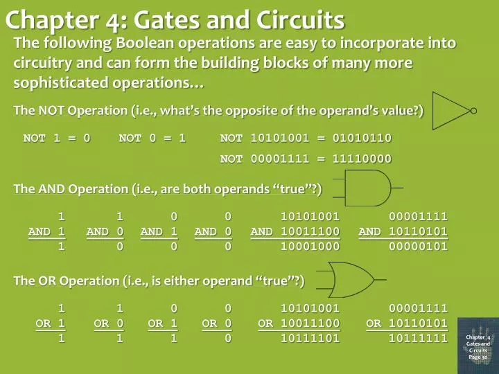
Chapter 4: Gates and Circuits The following Boolean operations are easy to incorporate into circuitry and can form the building blocks of many more sophisticated operations… The NOT Operation (i.e., what’s the opposite of the operand’s value?) NOT 1 = 0 NOT 0 = 1 NOT 10101001 = 01010110 NOT 00001111 = 11110000 The AND Operation (i.e., are both operands “true”?) 1 AND 1 1 1 AND 0 0 0 AND 1 0 0 AND 0 0 10101001 AND 10011100 10001000 00001111 AND 10110101 00000101 The OR Operation (i.e., is either operand “true”?) 1 OR 1 1 1 OR 0 1 0 OR 1 1 0 OR 0 0 10101001 OR 10011100 10111101 00001111 OR 10110101 10111111 Chapter 4 Gates and Circuits Page 30
More Boolean Operators The NAND Operation (“NOT AND”) 1 NAND 1 0 1 NAND 0 1 0 NAND 1 1 0 NAND 0 1 10101001 NAND 10011100 01110111 00001111 NAND 10110101 11111010 The NOR Operation (“NOT OR”) 1 NOR 1 0 1 NOR 0 0 0 NOR 1 0 0 NOR 0 1 10101001 NOR 10011100 01000010 00001111 NOR 10110101 01000000 The XOR Operation (“Exclusive OR”, i.e, either but not both is “true”) 1 XOR 1 0 1 XOR 0 1 0 XOR 1 1 0 XOR 0 0 10101001 XOR 10011100 00110101 00001111 XOR 10110101 10111010 Chapter 4 Gates and Circuits Page 31
Transistors Transistors are relatively inexpensive mechanisms for implementing the Boolean operators. In addition to the input connection (the base) Transistors are connected to both a power source and a voltage dissipating ground. Essentially, when the input voltage is high, an electric path is formed within the transistor that causes the power source to be drained to ground. When the input voltage is low, the path is not created, so the power source is not drained. Chapter 4 Gates and Circuits Page 32
Using Transistors to Create Logic Gates A NOT gate is essentially implemented by a transistor all by itself. A NAND gate uses a slightly more complex setup in which both inputs would have to be high to force the power source to be grounded. Use the output of a NAND gate as the input to a NOT gate to produce an AND gate, A NOR gate grounds the power source if either or both of the inputs are high. Use the output of a NOR gate as the input to a NOT gate to produce an OR gate.. Chapter 4 Gates and Circuits Page 33
How to Use Logic Gates for Arithmetic ANDs and ORs are all well and good, but how can they be used to produce binary arithmetic? Let’s start with simple one-bit addition (with a “carry” bit just in case someone tries to add 1 + 1!). Notice that the sum bit always yields the same result as the XOR operation, and the carry bit always yields the same result as the AND operation! By combining the right circuitry, then, multiple-bit addition can be implemented, as well as the other arithmetic operations. Chapter 4 Gates and Circuits Page 34
Memory Circuitry With voltages constantly on the move, how can a piece of circuitry be used to retain a piece of information? In the S-R latch, as long as the S and R inputs remain at one, the value of the Q output will never change, i.e., the circuit serves as memory! To set the stored value to one, merely set the S input to zero (for just an instant!) while leaving the R input at one. To set the stored value to zero, merely set the R input to zero (for just an instant!) while leaving the S input at one. Question: What goes wrong if both inputs are set to zero simultaneously? Chapter 4 Gates and Circuits Page 35
Integrated Circuits How does all of that elaborate circuitry get placed on the tiny microchips used in modern computers? A clean silicon wafer is oxidized to produce a thin layer of silicon dioxide, which is then coated with a radiation-sensitive film. The wafer is masked by lithography to expose it selectively to ultraviolet light, which causes the film layer to become dissolvable. Light-exposed areas are dissolved, exposing parts of the silicon dioxide layer, which are removed by an etching process. The remaining film is removed in a liquid bath. The areas of silicon exposed by the etching process are negatively charged by exposure to either arsenic or phosphorus vapor at high temperatures The areas covered by silicon dioxide remain positively charged. The silicon dioxide is removed The wafer is oxidized again. An opening is etched down to the positively charged silicon using a reverse mask. Another oxidation cycle forms a thin layer of silicon dioxide on the positively charged region of the wafer. Windows are etched in the negatively charged silicon areas in preparation for metal deposits. Chapter 4 Gates and Circuits Page 36