Download
1 / 53
540 likes | 564 Views
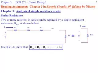
ENT 114: CIRCUIT THEORY. Chapter 4: Series dc Circuits. Series circuits. All circuits have three common attributes. These are:. 1. A source of voltage. 2. A load. 3. A complete path. A series circuit is one that has. only one current path.

E N D
ENT 114: CIRCUIT THEORY Chapter 4: Series dc Circuits
Series circuits All circuits have three common attributes. These are: 1. A source of voltage. 2. A load. 3. A complete path. A series circuit is one that has only one current path.
Two types of current are readily available, direct current (dc) and sinusoidal alternating current (ac) • We will first consider direct current (dc) • The direction of conventional flow ( Iconventional) is a opposite to that of electron flow ( Ielectron).
By following the direction of conventional flow • There is a rise in potential across the battery (- to + ) • Drop in potential across the resistor ( + to - )
For single-voltage-source dc circuits, conventional current flow always passes from a low potential to a high potential when passing through a voltage source
Conventional current flow always passes from a high to a low potential when passing through a resistor for any number of voltage source in the same circuit.
For example, the resistors in a series circuit are 680 W, 1.5 kW, and 2.2 kW. What is the total resistance? SERIES RESISTOR The total resistance of resistors in series is the sum of the individual resistors. 4.38 kW
Example 4.1 Determine the total resistance of the series connection in Figure 5.1. Figure 5.1
SERIES RESISTORS • When series resistors have the same value, • Where N = the number of resistors in the string. • The total series resistance is not affected by the order in which the components are connected.
Example 4.2 Determine the total resistance of the series resistor in Figure 5.2.
For example, the reading on the first ammeter is 2.0 mA, What do the other meters read? 2.0 mA SERIES CIRCUITS Series circuit rule for current: Because there is only one path, the current everywhere is the same. 2.0 mA 2.0 mA 2.0 mA
SERIES CIRCUITS • Total resistance (RT) is all the source “sees.” • Once RT is known, the current drawn from the source can be determined using Ohm’s law: • Since Vs is fixed, the magnitude of the source current will be totally dependent on the magnitude of RT .
SERIES CIRCUITS • The polarity of the voltage across a resistor is determined by the direction of the current. • Current entering a resistor create a drop in voltage with the polarity indicated in Figure (a). • Reverse the direction the polarity will reverse, Figure (b)
SERIES CIRCUIT Using voltmeters to measure the voltages across the resistors
Vs SERIES CIRCUITS • The magnitude of the voltage drop across each resistor can be found by applying Ohm’s Law using only the resistance of each resistor. • That is,
Vs Example 4.3 For the series circuit in Figure 4.3: • Find the total resistance RT • Calculate the resulting source current IS . • Determine the voltage across each resistor. Figure 4.3
Vs Example 4.4 For the series circuit in Figure 4.4: • Find the total resistance RT • Calculate the resulting source current IS and indicate its direction on the circuit. • Find the voltage across resistor R2 and indicate the polarity on the circuit. Figure 4.4
Vs Figure 4.5 Example 4.5 Given RT and I3 , calculate R1 and Vs
Question: What is the total voltage if one battery is reversed? VOLTAGE SOURCE IN SERIES Where n= 1,2,3,4,n….. Voltage sources in series add algebraically. For example, the total voltage of the sources shown is 27 V IS 9 V
V1 V1 V2 V2 VT VT V3 V3 Reducing series dc voltage sources to a single source. • By following the direction of conventional flow: • - There is a rise in potential across the battery (- to + ) • - There is drop in potential across the resistor ( + to - )
Continuing with the previous example, complete the parameters listed in the Table. I1= R1= 0.68 kWV1= P1= I2= R2= 1.50 kWV2= P2= I3= R3= 2.20 kWV3= P3= IT= RT= 4.38 kWVS= 12 V PT= Series circuit Tabulating current, resistance, voltage and power is a useful way to summarize parameters in a series circuit. 2.74 mA 1.86 V 5.1 mW 2.74 mA 4.11 V 11.3 mW 2.74 mA 6.03 V 16.5 mW 2.74 mA 32.9 mW
The algebraic sum of all the voltages around a closed path is zero. In other words, the sum of all the voltage drops around a single closed path in a circuit is equal to the total source voltage in that closed path. KIRCHOFF’S VOLTAGE LAW Kirchhoff’s voltage law is generally stated as: or KVL applies to all circuits, but you must apply it to only one closed path. In a series circuit, this is (of course) the entire circuit.
Vs KIRCHOFF’S VOLTAGE LAW The algebraic sum of all the voltages around a closed path is zero. Which can be written as the sum of all the voltage drops around a single closed path in a circuit is equal to the total source voltage in that closed path.
Vs2 Vs1 Figure 4.6 Example 4.6 Use Kirchoff’s voltage law to determine the unknown voltage for the circuit in Fig 4.6
Vs Example 4.7 Determine the unknown for the circuit in Fig. 4.7.
Example 4.8 Determine the unknown for the circuit in Fig. 4.8.
Example 4.9 Determine the unknown for the circuit in Fig. 4.9.
Example 5.0 • Determine V1 using KVL • Determine the current I1 • Find R2 10 Ω I1
VOLTAGE DIVISION IN A SERIES CIRCUIT • The voltage across the series resistive elements will divide as the magnitude of the resistance levels. • The greater the value of a resistor in a series circuit, the more of the applied voltage it will capture.
VOLTAGE DIVISION IN A SERIES CIRCUIT • The ratio of the voltage across series resistors will be the same as the ratio of their resistance level Notice the difference in the resistance magnitude but the voltage still remain the same
VOLTAGE DEVIDER RULE • The VDR permits determining the voltage levels of a circuit without first finding the current of the circuit.
VOLTAGE DEVIDER RULE First, determine the total resistance as follows: Then Apply Ohm’s law to each resistor: Vs The resulting format for V1 and V2 is
The voltage drop across any given resistor in a series circuit is equal to the value of that resistor times the total applied voltage divided by the total resistance of the series configuration Question: Assume R1 is twice the size of R2. What is the voltage across R1? VOLTAGE DEVIDER RULE Voltage divider rule states that 8 V
Applying the voltage divider formula: Voltage divider Example: What is the voltage across R2? Solution: Notice that 40% of the source voltage is across R2, which represents 40% of the total resistance. The total resistance is 25 kW.
Voltage divider Voltage dividers can be set up for a variable output using a potentiometer. In the circuit shown, the output voltage is variable. Question: What is the largest output voltage available? 5.0 V
} PT = 0.5 W Power in Series Circuits Example: Use the voltage divider rule to find V1 and V2. Then find the power in R1 and R2 and PT. Solution: The power dissipated by each resistor is: Applying the voltage divider rule:
Interchanging Series Elements • Elements of a series circuit can be interchanged without affecting the total resistance, current, or power to each element • In the Figures below, resistors 2 and 3 are interchanged without affecting the total resistance Insert Fig 5.19 Insert Fig 5.20
Notation Voltage sources and grounds Ground symbol Voltage source symbol
Notation 3 ways to sketch the same series dc circuit
Notation • Double-subscript notation • Because voltage is an “across” variable and exists between two points, the double-subscript notation defines differences in potential. • The double-subscript notation Vab specifies point a as the higher potential. If this is not the case, a negative sign must be associated with the magnitude of Vab . • The voltage Vab is the voltage at point (a) with respect to point (b).
Notation • Single-subscript notation • The single-subscript notation Va specifies the voltage at point a with respect to ground (zero volts). If the voltage is less than zero volts, a negative sign must be associated with the magnitude of Va .
Notation • General Relationship • If the voltage at points a and b are known with respect to ground, then the voltage Vab can be determined using the following equation: Vab = Va – V b
Question: What are VA, VB, and VAB for the circuit shown? Circuit Ground The term “ground” typically means a common or reference point in the circuit. Voltages that are given with respect to ground are shown with a single subscript. For example, VA means the voltage at point A with respect to ground. VB means the voltage at point B with respect to ground. VAB means the voltage between points A and B. VA = 12 V VB = 8 V VAB = 4 V
Example 5.1 Determined voltage Vab when Va = 10 V and Vb = 4V
Example 5.2 • Determined voltage Vab for the condition in the figure above • Note the negative sign to reflect the fact that point b is at higher potential than point a.
Example 5.3 • Determined voltage Vab for the condition in the figure