Download
1 / 22
220 likes | 333 Views
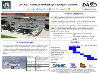
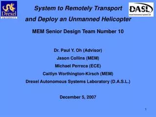
System to Remotely Transport and Deploy an Unmanned Helicopter. MEM Senior Design Team Number 10. Dr. Paul Y. Oh (Advisor) Jason Collins (MEM) Michael Perreca (ECE) Caitlyn Worthington-Kirsch (MEM) Drexel Autonomous Systems Laboratory (D.A.S.L.) December 5, 2007. The Problem.

E N D
System to Remotely Transport and Deploy an Unmanned Helicopter MEM Senior Design Team Number 10 Dr. Paul Y. Oh (Advisor) Jason Collins (MEM) Michael Perreca (ECE) Caitlyn Worthington-Kirsch (MEM) Drexel Autonomous Systems Laboratory (D.A.S.L.) December 5, 2007
The Problem -Rescue workers need to know where the dangers are and where they can do the most good -UAVs have been shown to help provide situational awareness -Keep human crew away from danger http://newsimg.bbc.co.uk/media/images/44194000/jpg/_44194534_afp203bodybonita.jpg http://www.viewimages.com/Search.aspx?mid=51919023&epmid=1&partner=Google
Thresholds and Objectives
Leveling System Design Parameters -Allow UAV platform to remain level as the trailer pitches and rolls -Prevent movement beyond set limits -Latch UAV in place during transit -Prevent the platform from moving during UAV takeoff -Design to carry either SR-100 or SR-20 helicopter UAV
Leveling System Proposed Solution -Gimbal system to level platform -Breaks to dampen oscillation -Bump stops to prevent over travel
Leveling System Risks High Risk: -Counter weight based leveling system can lead to swinging under natural frequency stimulus Reduction: -Use controlled breaking to stop any swinging Medium Risk: -Trailer pitch sharply and cause UAV tail to impact trailer structure Reduction: -Set mechanical limits to prevent gimbal from moving too far
Dampening System Design Parameters Protect the helicopter and gimbal from ground vibration Support weight of the helicopter and gimbal Initial design: classic spring-dashpot system Protect the helicopter and gimbal from sideways and twisting motion New design using bowls and a rubber ball, supported by the TRIZ principles of Dynamics and Curvature
Dampening System Proposed Solution Compressible ball between two bowls Allows for sideways and twisting movement Transference of approximately 5% of vibration at 5 Hz Proof-of-concept model
Dampening System Risks • High Risk: • – Design Viability • Reduction: • Mitigated by construction and testing of proof-of-concept model • Medium Risk: • – Tuning and Adaptability • Reduction: • - Adjustable ball inflation allows for varying vibration control
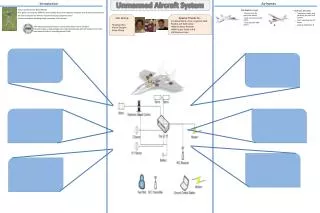
Control System Design Parameters • Must have the ability to be controlled/monitored remotely • Must support multiple analog inputs/outputs and provide real time processing • Remote Communications System • Ability to reprogram and adapt • Sturdy • Expandable
Control System Proposed Solution National Instruments Compact RIO • Features real time control and processing ability • Reconfigurable and Reprogrammable/Expandable • Sturdy and Rugged design • Proven to be able to process analog signals • -Relies on the LabVIEW programming environment • -Readily available from D.A.S.L.
Control System Risks High Risk:- Price of Equipment- Learning Curve LabVIEW ProgrammingReduction: D.A.S.L. hardware grant by National Instruments; Medium Risk:- Module AvailabilityReduction: Determine desired modules well in advance Low Risk:-Electrical Requirements( 9-35 V DC Input; 7-10 Watt Power Consumption)-Analog Signal Input and ControlReduction: Testing of proof-of-concept coding and design a common voltage electrical system
Trailer and Enclosure Design Parameters • Be able to fit into the Bossone Center and D.A.S.L. • Have a universal mounting system that can be used on multiple vehicles • Provide protection from debris and weather • Fit inside a U-Haul enclosed trailer for easy transportation • Light enough to be towed by D.I.A.S. I or II
Trailer and Enclosure Possible Solutions Pre-built 56”x56” Deck Over Trailer Pre-built 56”x90” Deck Over Trailer Pre-built 56”x90” Enclosed Deck Over Trailer Custom Built trailer by MEM Senior Design Team 10
Trailer and Enclosure Risks High Risk:-Weight-ExpandabilityReduction: Work hand in hand with trailer manufacturer to design for lightest application with best possibility of expansion Medium Risk:-Price-AvailabilityReduction: Locate a manufacturer near the Philadelphia Area with competitive pricing Low Risk:-Mounting styleReduction: Use of a standard Ball-Hitch style mounting system
Timeline Jan 14 – Design Freeze Jan 21 – all parts sourced and ordered Jan 28 – Begin building trailer, testing components as they are built Mar 10 – Full trailer testing begins May 5 – Final report and end of project
Budget *Average salaries provided by salary.com
Budgetary Options Options represent luxury, mid-range, and economy prototypes Tradeoff: More expensive = lower risk, more reliability Less expensive = more team man-hours Options in: Frame and gimbal materials Enclosure material Trailer base
Acknowledgements Dr. Paul Y. Oh D.A.S.L. Members MEM Senior Design Committee ECE Senior Design Committee All Those in Attendance
Thank You Questions? ?