Download
1 / 77
800 likes | 1.15k Views
3.3 Cell Switching (ATM). Asynchronous Transfer Mode (ATM) connection-oriented packet-switched network used in both WAN and LAN settings Q.2931: signaling (connection setup) protocol discover a suitable route across an ATM network

E N D
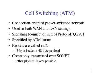
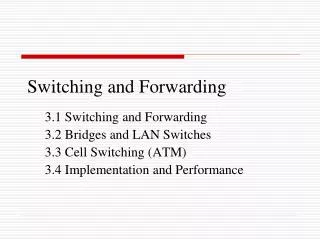
3.3 Cell Switching (ATM) • Asynchronous Transfer Mode (ATM) • connection-oriented packet-switched network • used in both WAN and LAN settings • Q.2931:signaling (connection setup) protocol • discover a suitable route across an ATM network • allocate resources at the switches along the circuit (to ensure the circuit a particular quality of service)
Cells • packets are called cells (fixed length) • 53-byte cell = 5-byte header + 48-byte payload • commonly transmitted over SONET • other physical layers possible
Variable vs. fixed-length packets • no optimal packet length • if small: high header-to-data overhead • if large: low utilization for small messages • variable-length packets • lower bound • minimum amount of information that needs to be contained in the packet • typically a header with no optional extensions
upper bound (set by a variety of factors) • the maximum FDDI packet size, for example, determines how long each station is allowed to transmit without passing on the token, and thus determines how long a station might have to wait for the token to reach it
fixed-length packets • it is easier to build hardware to do simple jobs, and the job of processing packets is simpler when you already know how long each one will be • if all packets are the same length, then each switching element takes the same time to do its job • packet vs. cell • most packet-switching technologies use variable-length packets • cells are fixed in length and small in size
Big vs. Small Packets • Small improves queue behavior • cell: finer control over the behavior of queues • examples • cell • cell length = 53 bytes • link speed = 100Mbps • the longest wait ≈ 53 × 8/100 = 4.24μs [exactly 4.04μs] for ATM
variable-length packets • maximum packet length = 4KB • link speed = 100Mbps • transmission time ≈ 4096 × 8/100 = 327.68μs [exactly 312.5μs] • a high priority packet that arrives just after the switch starts to transmit a 4KB packet will have to sit in the queue 327.68μs waiting for access to the link
cell: shorter queue length than that of packets • when a packet begins to arrive in an empty queue, the switch have to wait for the whole packet to arrive before it can start transmitting the packs on an outgoing link • it means that the link sits idle while the packet arrives • if you imagine a large packet being replaced by a “train” of small cells, then as soon as the first cell in the train has entered the queue, the switch can transmit it
example • variable-length packets • if two 4-KB packets arrived in a queue at about the same time • the link would sit idle for 327.68μs while these two packets arrive • at the end of that period we would have 8KB in the queue
Cell • if those same two packets were sent as trains of cells, then transmission of the cells could start 4.24μs after the first train started to arrive • at the end of 327.68μs, the link would have been active for a little over 323μs (≈ 327.68μs – 4.24μs) • there would be just over 4 KB of data left in the queue, not 8KB as before • shorter queues mean less delay for all the traffic
Small improves latency (for voice) • voice digitally encoded at 64Kbps (8-bit samples at 8KHz) • need full cell’s worth of voice samples before transmitting a cell • a sampling rate of 8KHz means that 1 byte is sampled every 125μs (= (1/8000) * 103), so the time it takes to fill an n-byte cell with samples is n × 125μs • a 1000-byte cells implies 125ms to collect a full cell of samples before you even start to transmit it to the receiver
Cell Format • Two different cell formats • User-Network Interface (UNI) format • host-to-switch format • interface between a telephone company and one of its customers • Network-Network Interface (NNI) format • switch-to-switch format • interface between a pair of telephone companies
User-Network Interface (UNI) • GFC (4 bits): Generic Flow Control(not wildly used) • Provide a means to arbitrate access to the link if the local site used some shared medium to connect to ATM • VPI (8 bits): Virtual Path Identifier • VCI (16 bits): Virtual Circuit Identifier • For now, we can think of them as a single 24-bite identifier that is used to identify a virtual conncection • Type (3 bits): management, user data • CLP (1 bit): Cell Loss Priority • A user or network element may set this bit to indicate cells that should be dropped preferentially in the event of overload
User-Network Interface (UNI) • …. • HEC (8 bits): Header Error Check (CRC-8) • Protecting the cell header is particularly important because an error in the VCI will cause the cell to be misdelivered • Network-Network Interface (NNI) • GFC becomes part of VPI field (no GFC and becomes 12-bit VPI)
Segmentation and Reassembly • Segmentation and Reassembly (SAR) • in ATM, the packets handed down from above are often larger than 48 bytes, and thus, will not fit in the payload of an ATM cell • solution • fragment the high-level message into low-level packets at the source • transmit the individual low-level packets over the network • reassemble the fragments back together at the destination
Segmentation is not unique to ATM • But it is much more of a problem than in a network with a maximum packet size of, say, 1,500 bytes • To address the issue, ATM Adaptation Layer was added
ATM Adaptation Layer (AAL) • a protocol layer sits between ATM and the variable-length packet protocols that might use ATM, such as IP • the AAL header simply contains the information needed by the destination to reassemble the individual cells back into the origins message
AAL AAL ■ ■ ■ ■ ■ ■ ATM ATM Segmentation and reassembly in ATM
Because ATM was designed to support all sorts of services, including voice, video, and data, it was felt that different services would have different AAL needs
ATM Adaptation Layer (AAL) • AAL1 and 2 designed for applications that need guaranteed bit rate (e.g., voice, video) • AAL 3/4 designed for packet data • AAL3 used by connection-oriented packet services (such as X25) • AAL4 used by connectionless services (such as IP) • AAL5 is an alternative standard for packet data • AAL3 and AAL4 are merged into one known as AAL ¾, so there are now four AALs
AAL 3/4 • AAL3/4 • provide enough information to allow variable-length packets to be transported across ATM network as a series of fixed-length cells • AAL supports the segmentation and reassembly process • the task of segmentation / reassembly involves two different packet formats • Convergence Sublayer Protocol Data Unit (CS-PDU) [AAL3/4 packet format] • ATM cell format for AAL3/4
0 ─ 24 8 8 8 16 < 64 KB 8 16 CPI Btag BASize User data Pad 0 Etag Len • Convergence Sublayer Protocol Data Unit (CS-PDU) • PDU (Protocol Data Unit), a new name for packet • CS-PDU defines a way of encapsulating variable-length PDUs prior to segmenting them into cells • the PDU passed down to the AAL layer is encapsulated by adding a header and a trailer [CS-PDU header and a trailer], and the resultant CS-PDU is segmented into ATM cells
encapsulate (header & trailer) AAL 3/4 packet(CS-PDU) segment PDU ATM cell Encapsulation and segmentation
0 ─ 24 8 8 8 16 < 64 KB 8 16 CPI Btag BASize User data Pad 0 Etag Len • CS-PDU format • CPI (8 bits): Common Part Indicator (version field) • Only the value 0 is currently defined • Btag/Etag (8 bits): Beginning and Ending tag • BASize (Buffer Allocation) (8 bits): a hint to the reassembly process as to how much buffer space to allocate for the reassembly • Pad: make sure the data is one byte less than a multiple of 4 bytes • 0-filled byte ensures the trailer is 32 bite • Len (16 bits): length of the PDU
0 ─ 24 8 8 8 16 < 64 KB 8 16 CPI Btag BASize User data Pad 0 Etag Len ATM Adaptation Layer 3/4 packet format
In addition to CS-PDU header and trailer, AAL 3/4 specifies a AAL 3/4 header and trailer[AAL 3/4 header and trailer] • The CS-PDU is segmented into 44-byte chunks, an AAL 3/4 header and trailer is attracted to each one, bringing it up to 48 bytes, which is then carried as the payload of an ATM cell
ATM Cell Format (AAL3/4) • Type (2 bits) • SEQ (4 bits) • sequence number • detect cell loss or misordering • MID (10 bits) • multiplexing identifier • multiplex several PDUs onto a single connection • Payload (352 bits;44 bytes) • the segmented CS-PDU chunk AAL3/4 Type field
Length (6 bits) • number of bytes of PDU contained in this cell • it must be 44 for BOM and COM cells • CRC-10 • error detection anywhere in the 48-byte cell payload
5 bytes 2 bytes 44 bytes 2 bytes ATM header AAL 3/4 header 44-byte chunk AAL 3/4 trailer 5 bytes 48 bytes ATM header Payload ATM cell format for AAL3/4
Encapsulation and segmentation for AAL3/4 • the user data is encapsulated with the CS-PDU header and trailer • the CS-PDU is then segmented into 44-bye payloads, which are encapsulated as ATM cells by adding the AAL3/4 header and trailer as well as the 5-byte ATM header • the last cell is only partially filled whenever the CS-PDU is not an exact multiple of 44 bytes
With 44 bytes of data to 9 bytes of header, the best possible bandwidth utilization would be 83%
AAL5 AAL 5 packet(CS-PDU) segment encapsulate PDU ATM cell
< 64 KB 0 ─ 47 bytes 16 16 32 Data Pad Reserved Len CRC-32 • CS-PDU Format • Data portion • trailer (8-byte) • 2-byte Reserved + 2-byte Len + 4-byte CRC-32 • Pad (up to 47 bytes) • so trailer always falls at end of ATM cell • Length • size of PDU (data only) • CRC-32 (detects missing or misordered cells)
< 64 KB 0 ─ 47 bytes 16 16 32 Data Pad Reserved Len CRC-32 ATM Adaptation Layer 5 packet format
Encapsulation and segmentation for AAL5 • user data is encapsulated to form a CS-PDU • the resulting PDU is then cut up into 48-byte chunks, which are carried directly inside the payload of ATM cells without any further encapsulation
3.3.3 Virtual Path • ATM uses a 24-bit identifier for vircuit circuits • 8-bit virtual path identifier (VPI) • 16-bit virtual circuit identifier (VCI)
Example • a corporation has two sites that connect to a public ATM network, and that at each site the corporation has a network of ATM switches • we could establish a virtual path between two sites using only the VPI field • within the corporate sites, however, the full 24-bit space is used for switching
Advantage of virtual path • although there may be thousands or millions of virtual connections across the public network, the switches in the public network behave as if there is only one connection • there needs to be much less connection-state information stored in the switches, avoiding the need for big, expensive tables of per-VCI information