Download
1 / 68
690 likes | 707 Views
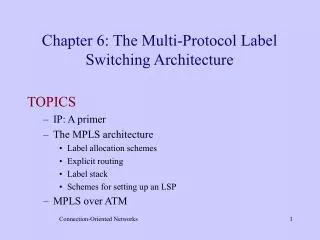
ATM and Multi-Protocol Label Switching (MPLS). By Behzad Akbari Fall 2008. These slides are based in parts on the slides of J. Kurose (UMASS) and Shivkumar (RPI). Outline. ATM basics IP over ATM MPLS basics MPLS VPN MPLS traffic engineering. Asynchronous Transfer Mode: ATM.

E N D
ATM and Multi-Protocol Label Switching(MPLS) By Behzad Akbari Fall 2008 These slides are based in parts on the slides of J. Kurose (UMASS) and Shivkumar (RPI)
Outline • ATM basics • IP over ATM • MPLS basics • MPLS VPN • MPLS traffic engineering
Asynchronous Transfer Mode: ATM • 1990’s/00 standard for high-speed (155Mbps to 622 Mbps and higher) Broadband Integrated Service Digital Network architecture • Goal:integrated, end-end transport of carry voice, video, data • meeting timing/QoS requirements of voice, video (versus Internet best-effort model) • “next generation” telephony: technical roots in telephone world • packet-switching (fixed length packets, called “cells”) using virtual circuits
AAL AAL ATM ATM ATM ATM physical physical physical physical end system switch switch end system ATM architecture • adaptation layer: only at edge of ATM network • data segmentation/reassembly • roughly analagous to Internet transport layer • ATM layer: “network” layer • cell switching, routing • physical layer
ATM: network or link layer? Vision: end-to-end transport: “ATM from desktop to desktop” • ATM is a network technology Reality: used to connect IP backbone routers • “IP over ATM” • ATM as switched link layer, connecting IP routers IP network ATM network
AAL AAL ATM ATM ATM ATM physical physical physical physical end system switch switch end system ATM Adaptation Layer (AAL) • ATM Adaptation Layer (AAL): “adapts” upper layers (IP or native ATM applications) to ATM layer below • AAL present only in end systems, not in switches • AAL layer segment (header/trailer fields, data) fragmented across multiple ATM cells • analogy: TCP segment in many IP packets
ATM Adaptation Layer (AAL) [more] Different versions of AAL layers, depending on ATM service class: • AAL1: for CBR (Constant Bit Rate) services, e.g. circuit emulation • AAL2: for VBR (Variable Bit Rate) services, e.g., MPEG video • AAL5: for data (eg, IP datagrams) User data AAL PDU ATM cell
ATM Layer Service: transport cells across ATM network • analogous to IP network layer • very different services than IP network layer Guarantees ? Network Architecture Internet ATM ATM ATM ATM Service Model best effort CBR VBR ABR UBR Congestion feedback no (inferred via loss) no congestion no congestion yes no Bandwidth none constant rate guaranteed rate guaranteed minimum none Loss no yes yes no no Order no yes yes yes yes Timing no yes yes no no
ATM Layer: Virtual Circuits • VC transport: cells carried on VC from source to dest • call setup, teardown for each call before data can flow • each packet carries VC identifier (not destination ID) • every switch on source-dest path maintain “state” for each passing connection • link,switch resources (bandwidth, buffers) may be allocated to VC: to get circuit-like perf. • Permanent VCs (PVCs) • long lasting connections • typically: “permanent” route between to IP routers • Switched VCs (SVC): • dynamically set up on per-call basis
ATM VCs • Advantages of ATM VC approach: • QoS performance guarantee for connection mapped to VC (bandwidth, delay, delay jitter) • Drawbacks of ATM VC approach: • Inefficient support of datagram traffic • one PVC between each source/dest pair) does not scale (N*2 connections needed) • SVC introduces call setup latency, processing overhead for short lived connections
ATM Layer: ATM cell • 5-byte ATM cell header • 48-byte payload • Why?: small payload -> short cell-creation delay for digitized voice • halfway between 32 and 64 (compromise!) Cell header Cell format
ATM cell header • VCI: virtual channel ID • will change from link to link thru net • PT:Payload type (e.g. RM cell versus data cell) • CLP: Cell Loss Priority bit • CLP = 1 implies low priority cell, can be discarded if congestion • HEC: Header Error Checksum • cyclic redundancy check
ATM Physical Layer (more) Two pieces (sublayers) of physical layer: • Transmission Convergence Sublayer (TCS): adapts ATM layer above to PMD sublayer below • Physical Medium Dependent: depends on physical medium being used TCS Functions: • Header checksumgeneration: 8 bits CRC • Cell delineation • With “unstructured” PMD sublayer, transmission of idle cells when no data cells to send
ATM Physical Layer Physical Medium Dependent (PMD) sublayer • SONET/SDH: transmission frame structure (like a container carrying bits); • bit synchronization; • bandwidth partitions (TDM); • several speeds: OC3 = 155.52 Mbps; OC12 = 622.08 Mbps; OC48 = 2.45 Gbps, OC192 = 9.6 Gbps • TI/T3: transmission frame structure (old telephone hierarchy): 1.5 Mbps/ 45 Mbps • unstructured: just cells (busy/idle)
IP-Over-ATM IP over ATM • replace “network” (e.g., LAN segment) with ATM network • ATM addresses, IP addresses Classic IP only • 3 “networks” (e.g., LAN segments) • MAC (802.3) and IP addresses ATM network Ethernet LANs Ethernet LANs
app transport IP AAL ATM phy app transport IP Eth phy ATM phy ATM phy IP AAL ATM phy Eth phy IP-Over-ATM
Datagram Journey in IP-over-ATM Network • at Source Host: • IP layer maps between IP, ATM dest address (using ARP) • passes datagram to AAL5 • AAL5 encapsulates data, segments cells, passes to ATM layer • ATM network:moves cell along VC to destination • at Destination Host: • AAL5 reassembles cells into original datagram • if CRC OK, datagram is passed to IP
IP-Over-ATM Issues: • IP datagrams into ATM AAL5 PDUs • from IP addresses to ATM addresses • just like IP addresses to 802.3 MAC addresses! ATM network Ethernet LANs
IP MPLS+IP ATM TDM MPLS: Best of Both Worlds CIRCUITSWITCHING PACKETROUTING HYBRID Caveat: one cares about combining the best of both worlds only for large ISP networks that need both features! Note: the “hybrid” also happens to be a solution that bypasses IP-over-ATM mapping woes!
History: Ipsilon’s IP Switching: Concept Hybrid: IP routing (control plane) + ATM switching (data plane)
Ipsilon’s IP Switching ATM VCs setup when new IP “flows” seen, I.e., “data-driven” VC setup
Tag Switching Key difference: tags can be setup in the background using IP routing protocols (I.e. control-driven VC setup)
Background • It was meant to improve routing performance on the Internet • Routing is difficult using CIDR (longest prefix matching) • Using the label-swapping paradigm to optimize network performance • MPLS is similar to virtual circuits • Only a fixed-sized label is used (like a VCID) with local scope • It is very datagram oriented though • It uses IP addressing and IP routing protocols
Goals of MPLS • To enable IP capability on devices that cannot handle IP traffic • Making cell switches behave as routers • Increased performance • Using the label-swapping paradigm to optimize network performance • Forward packets along “explicit routes” (pre-calculated routes not used in “regular” routing) • MPLS also permits explicit backbone routing, which specifies in advance the hops that a packet will take across the network. • This should allow more deterministic, or predictable, performance that can be used to guarantee QoS • To support certain virtual private network services
IP Regular Destination Based Forwarding Address Prefix Address Prefix Address Prefix I/F I/F I/F 128.89 128.89 128.89 1 0 0 171.69 1 171.69 1 … … … … 128.89 0 0 1 128.89.25.4 Data 0 Data 128.89.25.4 1 128.89.25.4 128.89.25.4 Data Data Packets Forwarded Based on IP Address 171.69
MPLS Example: Routing Information Out I’face OutLabel Out I’face OutLabel Out I’face OutLabel In Label Address Prefix In Label Address Prefix In Label Address Prefix 128.89 1 128.89 0 128.89 0 171.69 1 171.69 1 … … … … … … 128.89 0 0 1 You Can Reach 128.89 Thru Me You Can Reach 128.89 and 171.69 Thru Me 1 Routing Updates (OSPF, EIGRP, …) 171.69 You Can Reach 171.69 Thru Me
Labels for Destination-Based Forwarding • A label is allocated for each prefix in its table • The label is chosen locally • Think of them as indices into the routing table • Router advertises this to its neighbors • “label distribution protocol” (LDP) • Packets addressed to the prefix should, for efficiency, be tagged with the label. • The label of an incoming packet is “swapped” before being forwarded to the next router.
MPLS Example: Assigning Labels Out I’face Out I’face Out I’face In Label Address Prefix In Label Address Prefix In Label Address Prefix OutLabel OutLabel OutLabel - 128.89 1 4 4 128.89 0 9 9 128.89 0 - - 171.69 1 5 5 171.69 1 7 … … … … … … … … … … … … 128.89 0 0 1 Use Label 9 for 128.89 Use Label 4 for 128.89 and Use Label 5 for 171.69 1 Label Distribution Protocol (LDP) (downstream allocation) 171.69 Use Label 7 for 171.69
MPLS Example: Forwarding Packets Out I’face Out I’face Out I’face In Label Address Prefix In Label Address Prefix In Label Address Prefix OutLabel OutLabel OutLabel 4 128.89 - 1 4 128.89 0 9 9 128.89 0 - 5 - 171.69 1 5 171.69 1 7 … … … … … … … … … … … … 128.89 0 0 1 128.89.25.4 Data 128.89.25.4 Data 9 1 Data 4 128.89.25.4 Data 128.89.25.4 Label Switch Forwards Based on Label
1a. Existing routing protocols (e.g. OSPF, IS-IS) establish reachability to destination networks. 4. Edge LSR at egress removes(POP) label and delivers packet. 1b. Label Distribution Protocol (LDP) establishes label to destination network mappings. 2. Ingress Edge LSR receives packet, performs Layer 3 value-added services, and labels(PUSH) packets. 3. LSR switches packets using label swapping(SWAP) . MPLS Operation
Remarks • Rather than longest prefix-matching we use label matching • Labels can be very efficient, simply an index into the routing table • Regular IP routing is still used • E.g., we could use OSPF to determine the routes • Then we use labels for efficiency in per-hop routing • Note that a “Setup” phase (like in VC’s) is not used
Placement of “labels” For Ethernet, the “protocol number used” is 0x8847 for MPLS I.e., the “protocol number” of IP is not used. Thus, IP never sees the message!
Label Header • Header= 4 bytes, Label = 20 bits. • Can be used over Ethernet, 802.3, or PPP links • Contains everything needed at forwarding time 0 1 2 3 0 1 2 3 4 5 6 7 8 9 0 1 2 3 4 5 6 7 8 9 0 1 2 3 4 5 6 7 8 9 0 1 Label EXP S TTL Label = 20 bits EXP = Class of Service, 3 bits S = Bottom of Stack, 1 bit TTL = Time to Live, 8 bits
Some Definitions • Forwarding Equivalence Class (FEC): a group of IP packets which are forwarded in the same manner (e.g., over the same path, with the same forwarding treatment) • Labeled Switched Router (LSR): A router capable of supporting MPLS labels. • Labeled Switched Path: a sequence of LSR’s so that data can traverse the entire path using labels.
LSR LSR LER LER LSP IP1 IP1 IP1 IP1 IP2 IP2 IP1 IP2 #L3 #L2 #L2 #L3 #L1 #L1 IP2 IP2 Packets are destined for different address prefixes, but can be mapped to common path Traffic Aggregates: Forwarding Equivalence Classes • FEC = “A subset of packets that are all treated the same way by a router” • The concept of FECs provides for a great deal of flexibility and scalability • In conventional routing, a packet is assigned to a FEC at each hop (i.e. L3 look-up), in MPLS it is only done once at the network ingress
IP 47.1.1.1 1 47.1 3 3 2 1 1 2 47.3 3 47.2 2 IP 47.1.1.1 Label Switched Path (LSP)
Label Merging • When multiple input streams corresponding to the same FEC exit using the same MPLS label. • InLabel NextHop Label • Port 3 30 • 25 Port 3 30 Netw D Dest NextHop Label D Port 1 10 R2 R4 R1 Port 3 Port 1 Port 5 R3 Dest NextHop Label D Port 5 25
Non-Label Merging • Each source-destination pair has its own label at each LSR router. • InLabel NextHop Label • Port 3 5 • 25 Port 3 8 Netw D Dest NextHop Label D Port 1 10 R2 R4 R1 Port 3 Port 1 Port 5 R3 Dest NextHop Label D Port 5 25
Pushing-Requesting Labels • R2 can “push” a label to R1, indicating which label to use to reach D • R1 can “request” a label from R2 to be used to reach D. • If using non-merging, usually R1 requests a label from R2 Netw D R2 R4 R1
ATM • Most importantly, we can use ATM switches for IP • We can turn “ATM Cell switches” into “label switching routers” usually only by changing the software and not the hardware of the switch.
IP over ATM (Before MPLS) • We had every router with a VC over an ATM network to every other router • Known as an “overlay” network • Whole ATM network looked like a single “subnet” to the IP Routers • ATM switches are not aware that the payload is an IP packet
IP disassembly into ATM cells • IP becomes an “application” to the ATM layer. • IP packets have to be broken into small 48-byte pieces, and placed into ATM Cells • Cells are sent over the ATM circuit (e.g. from R1 to R6), the switches only see ATM Cells, not IP packet • At R6, the cells are regrouped and the IP packet restored
ATM switches as LSRs (using MPLS) • ATM switches are now “peers” of MPLS routers • No longer viewed as a single subnet, each link is now a subnet
Advantages of MPLS vs overlay • Each MPLS router has fewer “adjacencies” (i.e. neighbors) • This reduces the OSPF traffic to the router significantly • In OSPF you receive the topology of the entire network via each of your neighbors. • Each router now has a view of the entire topology • Not possible in overlay networks (ATM network “black box”) • Routers have better control of paths in case of link failures • In overlay networks, the ATM switches would do the rerouting • ATM switches may still support native ATM if desired.
How to route IP packets? • Can we send IP messages to our neighbors? • We can use a special VCID (say 0) to send IP messages to our neighbor. • Each node has a VCID 0 with each of its neighbors (a “single hop” VCID • Thus, to send an IP message to a neighbor • Disassemble the IP packet into ATM Cells • Send them on VCID 0 of the link of the desired neighbor • The neighbor reassembles the IP packet • Since we can send an IP message to any neighbor • This implies ATM LSR’s can execute ANY Internet protocol based on IP (e.g., OSPF, RIP, etc) and forward IP datagrams
End-to-end VC’s • Disassembly/reassembly at each hop is wasteful • It is better to establish an e-2-e VC for each source/destination pair, e.g., from R1 to R6 • From OSPF (or other mechanism), each router knows which other router is ATM or regular router • R1 “requests” a label from LSR1 for destination R6 • LSR1 requests a label from LSR3 for destination R6 • LSR3 requests a label from R6