Download
1 / 44
530 likes | 1.2k Views
Chapter 5 : Digital Communication Systems Chapter contents. 5.1 Overview of Digital Communication Systems Transmission schemes, communication link, Adv vs. Disadv 5.2 Digital Transmission – Pulse Modulation Pulse modulation method PWM, PAM, PPM, PCM 5.3 Pulse Code Modulation

E N D
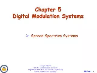
Chapter 5 : Digital Communication SystemsChapter contents • 5.1 Overview of Digital Communication Systems • Transmission schemes, communication link, Adv vs. Disadv • 5.2 Digital Transmission – Pulse Modulation • Pulse modulation method PWM, PAM, PPM, PCM • 5.3 Pulse Code Modulation • PCM operation, sampling, quantization • 5.4 Information Capacity, Bits, Bit Rate, Baud, M-ary encoding • 5.5 Digital Modulation • ASK, FSK. PSK • 5.6 Applications of Digital Communication Systems BENG 2413 Communication Principles Faculty of Electrical Engineering
5.1 Overview • Digital communications is the transfer of information (voice, data etc) in digital form. • Basic diagram of digital/data communications BENG 2413 Communication Principles Faculty of Electrical Engineering
5.1 Overview • If the information is in the analog form, it is converted to a digital form for transmission. At the receiver, it is re-converted to its analog form. • In some case, data needs to be changed to analog form to suit the transmission line (ex : internet/point-to-point data communication through the public switching telephone network) – the use of modem • Modem (from modulator-demodulator) is a device that modulates an analog carriersignal to encode digital information, and also demodulates such a carrier signal to decode the transmitted information • Function of modem at transmitter – converts digital data to analog signal that are compatible to the transmission line characteristics. BENG 2413 Communication Principles Faculty of Electrical Engineering
5.1 Overview • Transmission schemes for analog and digital signals BENG 2413 Communication Principles Faculty of Electrical Engineering
5.1.1 Communication links in digital transmission • Basic protocol of transmission : simplex, half-duplex, full duplex • Classification of communication link • Synchronous Channel – the transmitted and received data clocks are locked together. This requires that the data contains clocking information (self-clocking data). • Asynchronous Channel – the clocks on the transmitter and the receiver are not locked together. The data do not contain clocking information and typically contains start and stop bits to lock the systems together temporarily. BENG 2413 Communication Principles Faculty of Electrical Engineering
5.1.2 Digital vs Analog Communication Systems Advantages • Noise immunity • Digital signals are less susceptible than analog signals to interference caused by noise • Simple determination is made whether the pulse is above or below the prescribed reference level • Signal processing capability • Digital signals are better suited than analog signals for processing and combining for multiplexing purpose. • Much simpler to store digital signals compare to analog signals • Transmission rate of digital signals can be easily changed to suit different environments and to interface with different types of equipment. • Can also be sample instead of continuously monitored • A regenerative repeater along the transmission path prevent accumulation of noise along the path. It can detect a distorted digital signal and transmit a new clean signal BENG 2413 Communication Principles Faculty of Electrical Engineering
5.1.2 Digital vs Analog Communication Systems Advantages • Simpler to measure and evaluate than analog signals • Easier to compare the error performance of one digital system to another digital system. • Transmission error can be detected and corrected more easily and more accurately (error bit check). This gives very low error rate and high fidelity. • Digital hardware implementation is flexible and permits the use of microprocessors and digital switching. • Ability to carry a combination of traffics, e.g. telephone signals, data, coded video and teletext, if the medium has enough capacity. BENG 2413 Communication Principles Faculty of Electrical Engineering
5.1.2 Digital vs Analog Communication Systems Disadvantages • Bandwidth • Transmission of digitally encoded analog signals requires significantly more bandwidth than simply transmitting the original analog signal. • Circuit complexity • Analog signals must be converted to digital pulses prior to transmission and converted back to their original analog form at the receiver – additional encoding/decoding circuitry. • Requires precise time synchronization between the clocks in the transmitter and receiver. BENG 2413 Communication Principles Faculty of Electrical Engineering
5.2 Digital Transmission – Pulse Modulation • Mostly used modulation technique in digital transmission • Consists of several processes: • Sampling analog information signals • Converting those samples into discrete pulse • Transporting the pulses from a source to a destination over a physical transmission medium • Predominant method of pulse modulation – pulse width modulation (PWM), pulse position modulation (PPM), pulse amplitude modulation (PAM), pulse code modulation (PCM) • Pulse Width Modulation (PWM) • The width (active portion of the duty cycle) of a constant amplitude pulse is varied proportional to the amplitude to the amplitude of the analog signal at the time the signal is sampled. • Maximum analog signal amplitude produces the widest pulse, and the minimum analog signal amplitude produces the narrowest pulse. • All pulses have the same amplitude. BENG 2413 Communication Principles Faculty of Electrical Engineering
5.2 Digital Transmission – Pulse Modulation • Pulse Position Modulation (PPM) • The position of a constant-width pulse within a prescribed time slot is varied according to the amplitude of the sample of the analog signal. • The higher the amplitude of the sample, the farther to the right the pulse is positioned within the prescribed time slot. • The highest amplitude sample produces a pulse to the far right, and the lowest amplitude sample produces a pulse to the far left. • Pulse Amplitude Modulation (PAM) • the amplitude of a constant-width constant-position pulse is varied according to the amplitude of the sample of the analog signal. • The amplitude of a pulse coincides with the amplitude of the analog signal • PAM wave resemble the original analog signal more than the waveforms for PWM or PPM. BENG 2413 Communication Principles Faculty of Electrical Engineering
5.2 Digital Transmission – Pulse Modulation • Pulse Code Modulation (PCM) • Analog signal is sampled and then converted to a serial n-bit binary code for transmission. • Each code has the same number of bits and requires the same length of time for transmission. BENG 2413 Communication Principles Faculty of Electrical Engineering
5.2 Digital Transmission – Pulse Modulation Figure : Comparing between Pulse modulations: (a) analog signal; (b) sample pulse; (c) PWM; (d) PPM; (e) PAM; (f) PCM BENG 2413 Communication Principles Faculty of Electrical Engineering
5.3 Pulse Code Modulation (PCM) • Preferred method of communication within the public switched telephone network (PSTN). • with PCM it is easy to combine digitized voice and digital data into a single, high-speed digital signal and propagate it over either metallic or optical fiber cables. • Refer to figure of simplified block diagram of PCM system. At the transmitter • The bandpass filter limits the frequency of the analog input signal to the standard voice-band frequency range of 300 Hz ~ 3000 Hz. • The sample-and-hold circuit periodically samples the analog input signal and converts those samples to a multilevel PAM signal. • The analog-to-digital converter (ADC) converts the PAM samples to parallel PCM codes, which are converted to serial binary data in the parallel-to-serial converter. The output to the transmission line is a serial digital pulses. • The transmission line repeaters are placed at prescribed distances to regenerate the digital pulses. BENG 2413 Communication Principles Faculty of Electrical Engineering
5.3 Pulse Code Modulation (PCM) At the receiver • The serial-to parallel converter converts serial pulses received from the transmission line to parallel PCM codes. • The digital-to-analog converter (DAC) converts the parallel PCM codes to multilevel PAM signals. • The hold circuit is basically a low pass filter that converts the PAM signals back to its original analog form • An integrated circuit that performs the PCM encoding and decoding is called a codec (coder/decoder) BENG 2413 Communication Principles Faculty of Electrical Engineering
5.3 Pulse Code Modulation (PCM) • Block diagram of a single channel, simplex PCM transmission channel : BENG 2413 Communication Principles Faculty of Electrical Engineering
5.3.1 PCM Sampling • The function of the sampling circuit : • to periodically sampled the continually changing analog input and convert those samples to a series of constant-amplitude pulse that easily be converted to binary PCM code • 2 basic techniques for the sampling function : 1) Natural sampling • Tops of the sample pulses retain their natural shape during the sample interval. • Difficult for an ADC to convert the sample to a PCM code due to un-constant voltage. 2) Flat-top sampling • Most common method, used in the sample-and-hold circuit – periodically sample the continually changing analog input voltage and converts those samples to a series of constant-amplitude PAM voltage levels. BENG 2413 Communication Principles Faculty of Electrical Engineering
5.3.1 PCM Sampling Natural sampling Flat-top sampling BENG 2413 Communication Principles Faculty of Electrical Engineering
5.3.2 Sampling Rate • Sampling is a process of taking samples of information signal at a rate based on the Nyquist Sampling Theorem. • Nyquist Sampling Theorem – the original information signal can be reconstructed at the receiver with minimal distortion if the sampling rate in the pulse modulation signal is equal or greater than twice the maximum information signal frequency. where fs = minimum Nyquist sampling rate/frequency fm(max) = maximum information signal frequency BENG 2413 Communication Principles Faculty of Electrical Engineering
5.3.2 Sampling Rate • If fs is less than 2 times fm(max) an impairment called as alias or fold-over distortion occurs. BENG 2413 Communication Principles Faculty of Electrical Engineering
5.3.3 Quantization • Quantization – process of assigning the analog signal samples to a pre-determined discrete level. • The number of quantization levels, L depends on the number of bits per sample, n where where L = number of quantization level n = number of bits in binary to represent the value of the samples • The quantization levels are separated by a value of ΔV that can be defined as • ΔV is the resolution or step size of the quantization level. BENG 2413 Communication Principles Faculty of Electrical Engineering
5.3.3 Quantization • Ex : BENG 2413 Communication Principles Faculty of Electrical Engineering
5.3.3 Quantization • Ex (continue) : BENG 2413 Communication Principles Faculty of Electrical Engineering
5.3.3 Quantization • Quantization error/Quantization noise – error that is produced during the quantization process due to the difference between the original signal and quantized signal magnitudes. • Since a sample value is approximated by the midpoint of the sub-internal of height ΔV, in which the sample value falls, the maximum quantization error is ±ΔV/2. • Thus, the quantization error lies in the range (- ΔV/2, + ΔV/2). BENG 2413 Communication Principles Faculty of Electrical Engineering
5.3.4 Dynamic Range • the number of PCM bits transmitted per sample determined by determined by several factors – maximum allowable input amplitude, resolution and dynamic range. • Dynamic range (DR) – the ratio of the largest possible magnitude to the smallest possible magnitude (other than 0 V) that can be decoded by the DAC converter in the receiver. • mathematically expressed where DR = dynamic range (unitless ratio) Vmin = the quantum value (resolution) Vmax = the maximum voltage magnitude that can be discerned by the DAC’s in the receiver BENG 2413 Communication Principles Faculty of Electrical Engineering
5.3.4 Dynamic Range • Dynamic range is generally expressed as a dB value where DR = dynamic range (unitless ratio) Vmin = the quantum value (resolution) Vmax = the maximum voltage magnitude that can be discerned by the DAC’s in the receiver • the number of bits used for a PCM code depends on the dynamic range. The relationship between dynamic range and the number of bits in a PCM code is and for a minimum number of bits 2n – 1 = DR BENG 2413 Communication Principles Faculty of Electrical Engineering
5.3.4 Dynamic Range • Ex : For a PCM system with the following parameters, determine (a) minimum sample rate (b) minimum number of bits used in the PCM code (c) resolution (d) quantization error Maximum analog input frequency = 4 kHz Maximum decode voltage at the receiver = ±2.55V Minimum dynamic range = 46 dB BENG 2413 Communication Principles Faculty of Electrical Engineering
5.3.4 Coding Efficiency • Coding efficiency – ratio of the minimum number of bits required to achieve a certain dynamic range to the actual number of PCM bits used. • number of bits should include the sign bit ! BENG 2413 Communication Principles Faculty of Electrical Engineering
5.3.5 Signal-to-Quantization Noise Ratio • Generally, the quantization error or distortion caused by digitizing an analog sample expressed as an average signal power-to-average noise power ratio. • For a linear PCM codes (all quantization intervals have equal magnitudes), the signal power-to-quantizing noise power ratio is determined by where R = resistance (ohms) v = rms signal voltage (volts) q = quantization intervals (volts) v2/R = average signal power (watts) (q2/12)/R = average quantization noise power (watts) • if R is assume to be equal BENG 2413 Communication Principles Faculty of Electrical Engineering
5.3.6 Companding • Companding is the process of compressing and expanding to improve the dynamic range of a communication system. • a companding process is done by firstly compressing signal samples and then using a uniform quantization. The input-output characteristics of the compressor are shown below. • the compressor maps input signal increments Δx into larger increments Δy for a large input signals. • 2 compression laws recognized by CCITT : μLaw : North America & Japan A-Law : Europe & others BENG 2413 Communication Principles Faculty of Electrical Engineering
5.3.7 Line speed / Transmission bit rate • Line speed is the transmission bit rate at which serial PCM bits are clocked out of the PCM encoder onto the transmission line. • Line speed/transmission bit rate can be expressed as Line speed = samples/seconds x bits/sample line speed = transmission rate (bps) samples/second = sampling rate fs bits/sample = no of bits in the compressed PCM code BENG 2413 Communication Principles Faculty of Electrical Engineering
5.4 Parameters in Digital Modulation5.4.1 Information Capacity • Information capacity – a measure of how much information can be propagated through a communication systems and is a function of bandwidth and transmission time. • represents the number of independent symbols that can be carried through a system in a given unit of time • the most basic digital symbol used to represent information is the binary digit, or bit. • Bit rate – the number of bits transmission during one second and is expressed in bits per second (bps). • Bit rate is used to express the information capacity of a system. • mathematically expressed, information capacity I • refer to slides of chapter 1 ! BENG 2413 Communication Principles Faculty of Electrical Engineering
5.4.2 M-ary encoding • in an M-ary encoding, M represents a digit that corresponds to the number of conditions, levels, or combination possible for a given number of binary variables. • the number of bits necessary to produce a given number of conditions is expressed mathematically as where N = number of bits necessary M = number of conditions, levels, or combination possible with N bits • from above, the number of conditions possible with N bits can be expressed as • Ex : with 1 bit → 21 = 2 conditions 2 bits → 22 = 4 conditions 3 bits → 23 = 8 conditions BENG 2413 Communication Principles Faculty of Electrical Engineering
5.4.3 Baud and Minimum Bandwidth • Bit rate – refers to the rate of change of digital information, which is usually binary. • Baud – refers to the rate of change of a signal on a transmission medium after encoding and modulation have occurred. • Baud can be expressed as where Baud = symbol rate (baud per second) ts = time of one signaling element (seconds) signaling element = symbol • for a given bandwidth B, the highest theoretical bit rate is 2B. Using the multilevel signaling, the Nyquist formulation for channel capacity is BENG 2413 Communication Principles Faculty of Electrical Engineering
5.4.3 Baud and Minimum Bandwidth where fb = channel capacity (bps) B = minimum Nyquist bandwidth (Hertz) M = number of discrete signal or voltage levels • above formula can be rearranged to solve for the minimum bandwidth necessary to pass M-ary digitally modulated carrier as follow • since N = log2M above formula can be expressed as where N is the number of bits encoded into each signaling element (symbol). BENG 2413 Communication Principles Faculty of Electrical Engineering
5.5 Digital Modulation • Given an information signal which is digital and a carrier signal represented as follow : • A digitally modulated signal is produced as follow : • If the amplitude (V) of the carrier is varied proportional to the information signal, ASK (Amplitude Shift Keying) is produced. • If the frequency (f) of the carrier is varied proportional to the information signal, FSK (Frequency Shift Keying) is produced. • If the phase (θ) of the carrier is varied proportional to the information signal, PSK (Phase Shift Keying) is produced. • If both amplitude and phase are varied proportional to the information signal, QAM (Quadrature Amplitude Modulation) is produced. BENG 2413 Communication Principles Faculty of Electrical Engineering
5.5.1 Amplitude Shift Keying • digital information signal directly modulates the amplitude of the analog carrier. • mathematically, the modulated carrier signal is expressed as follow : (5.5-1) where vask(t) = amplitude-shift keying wave vm(t) = digital information (modulating) signal (volts) A/2 = unmodulated carrier amplitude (volts) ωc = analog carrier radian frequency • in the above (5.5-1), modulating signal vm(t) is a normalized binary waveform, where +1V = logic 1 and -1V = logic 0. BENG 2413 Communication Principles Faculty of Electrical Engineering
5.5.1 Amplitude Shift Keying • for a logic 1 input, vm(t) = +1V, and (5.5-1) reduces to • and for logic 0 input, vm(t) = -1V, and (5.5-1) reduces to • so the modulated wave vask(t), is either Acos(ωct) or 0, means the carrier is either “on” or “off”. ASK is sometimes referred as on-off keying (OOK). BENG 2413 Communication Principles Faculty of Electrical Engineering
5.5.1 Amplitude Shift Keying BENG 2413 Communication Principles Faculty of Electrical Engineering
5.5.2 Frequency Shift Keying • general expression for FSK : (5.5-2) where vfsk(t) = binary FSK waveform Vc = peak analog carrier amplitude fc = analog carrier center frequency (Hz) vm(t) = binary input (modulating signal) Δf = peak change (shift) in the analog carrier frequency • from (5.5-2), the peak shift in the carrier frequency (Δf) is proportional to the amplitude of the binary input signal vm(t). • the direction of the shift is determined by the polarity of signal ( 1 or 0 ). • the modulating signal vm(t) is a normalized binary waveform where a logic 1 = +1V and a logic 0 = -1V. BENG 2413 Communication Principles Faculty of Electrical Engineering
5.5.2 Frequency Shift Keying • for logic 1 input, vm(t) = +1, equation (5.5-2) becomes • for logic 0 input, vm(t) = -1, equation (5.5-2) becomes • the carrier center frequency fc is shifted (deviated) up and down in the frequency domain by the binary input signal as shown below. BENG 2413 Communication Principles Faculty of Electrical Engineering
5.5.2 Frequency Shift Keying BENG 2413 Communication Principles Faculty of Electrical Engineering
5.5.2 Frequency Shift Keying • mark (fm) = logic 1 frequency • space (fs) = logic 0 frequency BENG 2413 Communication Principles Faculty of Electrical Engineering
5.5.3 Phase Shift Keying • modulation technique that alters the phase of the carrier. • in a binary phase-shift keying (BPSK), where N (number of bits) = 1, M (number of output phases) = 2, one phase represents a logic 1 and another phase represents a logic 0. • as the input digital signal changes state (i.e. from 1 to 0 or 0 to 1), the phase of the output carrier shifts between two angles that are separated by 180º. BENG 2413 Communication Principles Faculty of Electrical Engineering
5.5.3 Phase Shift Keying BENG 2413 Communication Principles Faculty of Electrical Engineering