Download
1 / 40
420 likes | 567 Views
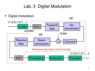
Chapter 5 Digital Modulation Systems. Spread Spectrum Systems. Huseyin Bilgekul EEE 461 Communication Systems II Department of Electrical and Electronic Engineering Eastern Mediterranean University. Introduction to Spread Spectrum.

E N D
Chapter 5Digital Modulation Systems • Spread Spectrum Systems Huseyin Bilgekul EEE 461 Communication Systems II Department of Electrical and Electronic Engineering Eastern Mediterranean University
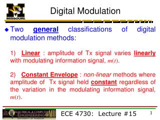
Introduction to Spread Spectrum • Problems such as capacity limits, propagation effects, synchronization occur with wireless systems • Spread spectrum modulation spreads out the modulated signal bandwidth so it is much greater than the message bandwidth • Independent code spreads signal at transmitter and despread the signal at receiver
Spread Spectrum Systems • Multiple access capability • Anti-jam capability • Interference rejection • Secret operation • Low probability of intercept • Simultaneous use of wideband frequency • Code division multiple access (CDMA)
Multiplexing • Multiplexing in 4 dimensions • space (si) • time (t) • frequency (f) • code (c) • Goal: Multiple use of a shared medium • Important: guard spaces needed! Channels ki k1 k2 k3 k4 k5 k6 c t c s1 t s2 f f c t s3 f
Frequency Division Multiplex • Separation of spectrum into smaller frequency bands • Channel gets band of the spectrum for the whole time • Advantages: • no dynamic coordination needed • works also for analog signals • Disadvantages: • waste of bandwidth if traffic distributed unevenly • inflexible • guard spaces Channels ki k3 k4 k5 k6 c f t
Time Division Multiplex • Channel gets the whole spectrum for a certain amount of time • Advantages: • only one carrier in themedium at any time • throughput high even for many users • Disadvantages: • precise synchronization necessary Channels ki k1 k2 k3 k4 k5 k6 c f t
Time and Frequency Division Multiplex • A channel gets a certain frequency band for a certain amount of time (e.g. GSM) • Advantages: • better protection against tapping • protection against frequency selective interference • higher data rates compared tocode multiplex • Precise coordinationrequired Channels ki k1 k2 k3 k4 k5 k6 c f t
Code Division Multiplex Channels ki • Each channel has unique code • All channels use same spectrum at same time • Advantages: • bandwidth efficient • no coordination and synchronization • good protection against interference • Disadvantages: • lower user data rates • more complex signal regeneration • Implemented using spread spectrum technology k1 k2 k3 k4 k5 k6 c f t
DS/SS PSK Signals Direct-sequence spread coherent phase-shift keying. (a) Transmitter. (b) Receiver.
Waveforms at the transmitter Tb Bit interval Tc Chip interval PG= Tb/Tc
Spread Spectrum Technology • Problem of radio transmission: frequency dependent fading can wipe out narrow band signals for duration of the interference • Solution: spread the narrow band signal into a broad band signal using a special code interference spread signal signal power power spread interference detection at receiver f f
Spread Spectrum Technology • Side effects: • coexistence of several signals without dynamic coordination • tap-proof • Alternatives: Direct Sequence (DS/SS), Frequency Hopping (FH/SS) • Spread spectrum increases BW of message signal by a factor N, Processing Gain
P P User signal Broadband interference Narrowband interference i) ii) f f Sender P P P iii) iv) v) f f f Receiver Effects of spreading and interference • The narrowband interference at the receiver is spread out so that the detected narrowband signal power is much lower.
channelquality 2 1 5 6 narrowband channels 3 4 frequency guard space channelquality 2 2 2 2 2 1 frequency spreadspectrum Spreading and frequency selective fading Narrowband signal spread spectrum channels • Wideband signals are less affected by frequency selective multipath channels
Direct Sequence Spread Spectrum (DSSS) I • Direct Sequence (DS) CDMA • m(t) is polar from a digital source ±1. • For BPSK modulation, gm(t) = Acm(t). The spreading waveform complex envelope gc(t) = c(t) c(t) is a polar spreading signal). • The resulting complex envelope of the SS signal becomes g(t) = Acm(t)c(t). • The spreading waveform is generated by using PN code generator. The pulse width of Tc is called the chip interval. • When a PN sequence has the maximum period of N chips, where N = 2r -1, it is called a maximum length sequence (m-sequence). There are certain very important properties of m-sequences:
Properties of Maximum Length Sequences • Balance Property: In each period of maximum-length sequence, the number of 1s is always one more than the number of 0s. • Run Property: Here, the 'run' represents a subsequence of identical symbols(1's or 0's) within one period of the sequence. One-half the run of each kind are of length one, one-fourth are length two, one-eighth are of length three, etc. • Correlation Property: The autocorrelation function of a maximum-length sequence is periodic, binary valued and has a period T=NTc where Tc is chip duration. • The autocorrelation function is
Maximum Length Sequences (a) Waveform of maximal-length sequence for length m 3 or period N 7. (b) Autocorrelation function. (c) Power spectral density.
Maximum Length Sequences Feedback shift register. Two different configurations of feedback shift register of length m 5. (a) Feedback connections [5, 2]. (b) Feedbackconnections [5, 4, 2, 1].
R(t) t -> -1/n nTc Tc -nTc Maximum Length Sequences • Codes are periodic and generated by a shift register and XOR • Maximum-length (ML) shift register sequences, m-stage shift register, length: n = 2m – 1 bits Output +
Generating PN Sequences • Take m=2 =>L=3 • cn=[1,1,0,1,1,0, . . .], usually written as bipolar cn=[1,1,-1,1,1,-1, . . .] Output +
Problems with m-sequences • Cross-correlations with other m-sequences generated by different input sequences can be quite high. • Easy to guess connection setup in 2m samples so not too secure. • In practice, Gold codes or Kasami sequences which combine the output of m-sequences are used.
DSSS • XOR the signal with pseudonoise (PN) sequence (chipping sequence) • Advantages • reduces frequency selective fading • in cellular networks • base stations can use the same frequency range • several base stations can detect and recover the signal • But, needs precise power control Tb user data 0 1 XOR Tc chipping sequence 0 1 1 0 1 0 1 0 1 1 0 1 0 1 = Resulting Signal 0 1 1 0 1 0 1 1 0 0 1 0 1 0
DSSS Transmitter and Receiver TRANSMITTER Spread spectrum Signal y(t)=m(t)c(t) Transmit signal user data m(t) X modulator radio carrier chipping sequence, c(t) RECIVER Correlator sampled sums Received signal data demodulator X integrator decision radio carrier Chipping sequence, c(t)
DS/SS Comments • Pseudonoise (PN) sequence chosen so that its autocorrelation is very narrow => PSD is very wide • Concentrated around t < Tc • Cross-correlation between two user’s codes is very small • Secure and Jamming Resistant • Both receiver and transmitter must know c(t) • Since PSD is low, hard to tell if signal present • Since wide response, tough to jam everything • Multiple access • If ci(t) is orthogonal to cj(t), then users do not interfere • Near/Far problem: Users must be received with the same power
Frequency Hopping Spread Spectrum (FH/SS) • A frequency-hopped SS (FH/SS) signal uses a gc(t) that is of FM type. There are M=2k hop frequencies controlled by the spreading code. • Discrete changes of carrier frequency • sequence of frequency changes determined via PN sequence • Two versions • Fast Hopping: several frequencies per user bit (FFH) • Slow Hopping: several user bits per frequency (SFH) • Advantages • frequency selective fading and interference limited to short period • uses only small portion of spectrum at any time • Disadvantages • not as robust as DS/SS • simpler to detect
Slow Frequency Hopping Illustrating slow-frequency hopping. (a) Frequency variation for one complete period of the PN sequence.(b) Variation of the dehopped frequency with time.
Fast Frequency Hopping Illustrating fast-frequency hopping.(a) Variation of the transmitter frequency with time. (b) Variation of the dehopped frequency with time.
FHSS (Frequency Hopping Spread Spectrum) II Tb user data 0 1 0 1 1 t f Td f3 slow hopping (3 bits/hop) f2 f1 t Td f f3 fast hopping (3 hops/bit) f2 f1 t Tb: bit period Td: dwell time
narrowband signal Spread transmit signal Transmitter user data modulator modulator hopping sequence frequency synthesizer Receiver received signal data demodulator demodulator hopping sequence frequency synthesizer FHSS Transmitter and Receiver
Applications of Spread Spectrum • In 1985 FCC opened 902-928 Mhz, 2400-2483Mhz and 5725-5850 Mhz bands for commercial SS use with unlicensed transmitters. • Cell phones • IS-95 (DS/SS) • GSM • Global Positioning System (GPS) • Wireless LANs • 802.11b
Performance of DS/SS Systems • Pseudonoise (PN) codes • Spread signal at the transmitter • Despread signal at the receiver • Ideal PN sequences should be • Orthogonal (no interference) • Random (security) • Autocorrelation similar to white noise (high at t=0 and low for t not equal 0)
Detecting DS/SS PSK Signals transmitter Spread spectrum Signal y(t)=m(t)c(t) transmit signal Bipolar, NRZ m(t) X X PN sequence, c(t) sqrt(2)cos(wct + q) receiver received signal z(t) w(t) data decision integrator LPF X X x(t) c(t) sqrt(2)cos(wct + q)
Optimum Detection of DS/SS PSK • Recall, bipolar signaling (PSK) and white noise give the optimum error probability • Not effected by spreading • Wideband noise not affected by spreading • Narrowband noise reduced by spreading
Signal Spectra • Effective noise power is channel noise power plus jamming (NB) signal power divided by N Tb Tc
Multiple Access Performance • Assume K users in the same frequency band, • Interested in user 1, other users interfere 4 6 5 1 3 2
Signal Model • Interested in signal 1, but we also get signals from other K-1 users: • At receiver,
Interfering Signal • After mixing and despreading (assume t1=0) • After LPF • After the integrator-sampler
At Receiver • m(t) =+/-1 (PSK), bit duration Tb • Interfering signal may change amplitude at tk • At User 1: • Ideally, spreading codes are Orthogonal:
Multiple Access Interference (MAI) Example of Performance Degradation N=8 N=32 • If the users are assumed to be equal power interferers, can be analyzed using the central limit theorem (sum of IID RV’s)
1 k Near/Far Problem • Performance estimates derived using assumption that all users have same power level • Reverse link (mobile to base) makes this unrealistic since mobiles are moving • Adjust power levels constantly to keep equal • K interferers, one strong interfering signal dominates performance • Can result in capacity losses of 10-30%