Download
1 / 36
360 likes | 521 Views
Principles of Computer Architecture Miles Murdocca and Vincent Heuring Chapter 5: Languages and the Machine. Chapter Contents. 5.1 The Compilation Process 5.2 The Assembly Process 5.3 Linking and Loading 5.4 Macros

E N D
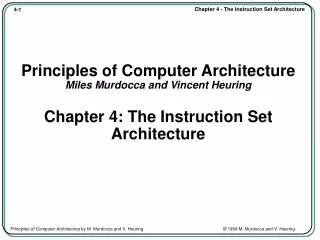
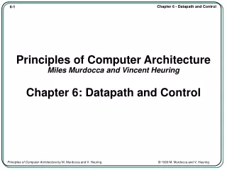
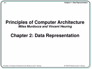
Principles of Computer ArchitectureMiles Murdocca and Vincent HeuringChapter 5: Languages and the Machine
Chapter Contents 5.1 The Compilation Process 5.2 The Assembly Process 5.3 Linking and Loading 5.4 Macros 5.5 Case Study: Extensions to the Instruction Set – The Intel MMX™ and Motorola AltiVec™ SIMD Instructions
The Compilation Process • Compilation translates a program written in a high level language into a functionally equivalent program in assembly language. • Consider a simple high-level language assignment statement: A = B + 4; • Steps involved in compiling this statement into assemby code: — Reducing the program text to the basic symbols of the language (for example, into identifiers such as A and B), denotations such as the constant value 4, and program delimiters such as = and +. This portion of compilation is referred to as lexical analysis. — Parsing symbols to recognize the underlying program structure. For the statement above, the parser must recognize the form: Identifier “=” Expression, where Expression is further parsed into the form: Identifier “+” Constant.Parsing is sometimes called syntactic analysis.
The Compilation Process — Name analysis: associating the names A and B with particular program variables, and further associating them with particular memory locations where the variables are located at run time. — Type analysis: determining the types of all data items. In the example above, variables A and B and constant 4 would be recognized as being of type int in some languages. Name and type analysis are sometimes referred to together as semantic analysis: determining the underlying meaning of program components. — Action mapping and code generation: associating program statements with their appropriate assembly language sequence. In the statement above, the assembly language sequence might be as follows: ld [B], %r0, %r1 ! Get variable B into a register. add %r1, 4, %r2 ! Compute the value of the expression st %r2, %r0, [A] ! Make the assignment.
The Assembly Process • The process of translating an assembly language program into a machine language program is referred to as the assembly process. • Production assemblers generally provide this support: — Allow programmer to specify locations of data and code. — Provide assembly-language mnemonics for all machine instructions and addressing modes, and translate valid assembly language statements into the equivalent machine language. — Permit symbolic labels to represent addresses and constants. — Provide a means for the programmer to specify the starting address of the program, if there is one; and provide a degree of assemble-time arithmetic. — Include a mechanism that allows variables to be defined in one assembly language program and used in another, separately assembled program. — Support macro expansion.
Assembly Example • We explore how the assembly process proceeds by “hand assembling” a simple ARC assembly language program.
Assembled Code ld [x], %r1 1100 0010 0000 0000 0010 1000 0001 0100 ld [y], %r2 1100 0100 0000 0000 0010 1000 0001 1000 addcc %r1,%r2,%r3 1000 0110 1000 0000 0100 0000 0000 0010 st %r3, [z] 1100 0110 0010 0000 0010 1000 0001 1100 jmpl %r15+4, %r0 1000 0001 1100 0011 1110 0000 0000 0100 15 0000 0000 0000 0000 0000 0000 0000 1111 9 0000 0000 0000 0000 0000 0000 0000 1001 0 0000 0000 0000 0000 0000 0000 0000 0000
Forward Referencing • An example of forward referencing:
Linking: Using .global and .extern • A .global is used in the module where a symbol is defined and a .extern is used in every other module that refers to it.
Linking and Loading: Symbol Tables • Symbol tables for the previous example:
Macro Definition • A macro definition for push:
Intel MMX (MultiMedia eXtensions) • Vector addition of eight bytes by the Intel PADDB mm0, mm1 instruction:
Intel and Motorola Vector Registers • Intel “aliases” the floating point registers as MMX registers. This means that the Pentium’s 8 64-bit floating-point registers do double-duty as MMX registers. • Motorola implements 32 128-bit vector registers as a new set, separate and distinct from the floating-point registers.
Addressing Modes • Four ways of computing the address of a value in memory: (1) a constant value known at assembly time, (2) the contents of a register, (3) the sum of two registers, (4) the sum of a register and a constant. The table gives names to these and other addressing modes.
Subroutine Linkage – Registers • Subroutine linkage with registers passes parameters in registers.
Subroutine Linkage – Data Link Area • Subroutine linkage with a data link area passes parameters in a separate area in memory. The address of the memory area is passed in a register (%r5 here).
Subroutine Linkage – Stack • Subroutine linkage with a stack passes parameters on a stack.
Stack Linkage Example • A C program illustrates nested function calls.
StackLinkageExample (cont’) • (a-f) Stack behavior during execution of the program shown in previous slide.
Stack Linkage Example (cont’) • (g-k) Stack behavior during execution of the C program shown previously.
Input and Output for the ISA • Memory map for the ARC, showing memory mapped I/O.
Touchscreen I/O Device • A user selecting an object on a touchscreen:
Flowchart for I/O Device • Flowchart illustrating the control structure of a program that tracks a touchscreen.
Byte Code for Java Program • Disassembled byte code for previous Java program. Location Code Mnemonic Meaning 0x00e3 0x10 bipush Push next byte onto stack 0x00e4 0x0f 15 Argument to bipush 0x00e5 0x3c istore_1 Pop stack to local variable 1 0x00e6 0x10 bipush Push next byte onto stack 0x00e7 0x09 9 Argument to bipush 0x00e8 0x3d istore_2 Pop stack to local variable 2 0x00e9 0x03 iconst_0 Push 0 onto stack 0x00ea 0x3e istore_3 Pop stack to local variable 3 0x00eb 0x1b iload_1 Push local variable 1 onto stack 0x00ec 0x1c iload_2 Push local variable 2 onto stack 0x00ed 0x60 iadd Add top two stack elements 0x00ee 0x3e istore_3 Pop stack to local variable 3 0x00ef 0xb1 return Return